Transcription of Installation / Setup Guide - ThunderMax
1 Part # 309-460 fo r 2001-2010 Softail , 2002-2007 Touring, & 2007-2009 XL Thank you for purchasing a ThunderMax ECM! Please read through the following instructions before beginning the Installation procedure. Following these instructions will ensure that the ECM is installed and Setup properly for optimal results. If you have any problems or questions, please refer to the TMaxII Tuning .pdf Manual, included on the CD (Help Menu) with this package. Record serial number NOW on your warranty card, and below for your records! Serial # TMRM All Models - Oxygen Sensor Installation Tips Your ThunderMax kit includes robust Wide-Band oxygen sensors that report data from every cylin der combustion event to the ThunderMax ECM for automatic air/fuel corrections. These sensors replace the factory supplied narrow-band sensors first used on 2007-2010 bikes and in most cases are direct bolt-in replacements.
2 2001-2006 models will require the addition of 18mm sensor bungs to the exhaust header pipes if yours don t currently have them installed. Installation of the wide band sensors into most bung-equipped headpipes presents no clearance problems; however, some pipe brands may require exhaust pipe modification or sensor bung relocation for interference-free Installation . The sensors must mount freely without contacting surrounding components. If this is not possible, do not attempt to bend or modify the sensor in any way as it is a sensitive electronic component and will be damaged if you do. Modify the pipe if required for clearance. W eld-in bungs are available for exhaust systems not equipped with bungs or if current bungs present clearance issues. Bungs should be located no more than 3-4 from the head/pipe connection (for ideal location, refer to the 2007 factory location).
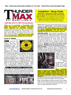
3 W eld-in bungs are available in straight or angled style from many industry sources; see video Installation link on page 8. After Installation , route the sensor harness away from the engine and along the frame when possible, above the lowest frame point to avoid the possibilit y of dragging ground during operation. Avoid routing harnesses where engine movement or sharp edges can contact and cut into the harnesses or connector pl ugs. Tie Installation / Setup Guide Please Note: This product is Legal in California only for racing vehicles which may never be used upon a highway. The user shall determine suitabili ty of the product for his or her use. Installation and use on a pollu tion- controll ed vehicle constitutes tampering under the EPA guidelin es and can lead to substantial fines. Review your application and check your local laws before installin g. the harnesses to the frame or existing component harnesses, taking care to avoid contact with any vibrating component that may chaff the sheathing or wires.
4 Some disassembly of bike components may be required for best harness routing. Remove any previously installed ancillary tuning device including oxygen sensor eliminators that may be plugged into the factory oxygen sensor harness. Step 1 Insert the TMaxII CD into your computer. TMaxII will automatically open the InstallShield W izard when the computer finds the CD-Rom. Follo w the instructions and install the software on your computer. All Models - A packet of dielectric grease is included with your ThunderMax . When installing the ECM, apply the provided dielectric grease to the inside lip of the ThunderMax ECM to ensure the rubber weather seal does not bind during Installation and across the clear case on the 36 pin ECM connector. Spread the grease across all of the female terminal openings, making sure the grease penetrates openings. This grease will greatly improve vital conductivity between the ThunderMax and the 36 pin connector.
5 Also apply dielectric grease to the ThunderMax oxygen sensor harness connector terminals for improved conductivity, and to the outer housing to prevent binding upon Installation to the ECM. Step 2 - Module Installation - Softail Models 309-460 Installation / Setup Guide 1 (Ski p ahead for other models) FX/FLST-A: Remove the seat to access the factory Electronic Control Module (ECM). Slide the fuse box to the left to release it from the plastic bracket. Open the fuse box and remove the main fuse. FX/FLST-B: Remove the batte ry cables (negative first) and remove battery from the motorcycle. Remove any previously installed ancillary tuning device including oxygen sensor eliminators that may be plugged into the factory oxygen sensor harness. FX/FLST-C: Remove the (4) mounting nuts holding the factory ECM in place and lift the ECM from the mounting bracket.
6 Depress the latch on the main connector and remove the factory ECM from the wiring harness. FX/FLST-F: Lift the steel fuse box mounting bracket to expose the rear of the plastic batte ry tray / wiring caddy. Firmly push the caddy forward to create space needed to feed the Front ThunderMax oxygen sensor harness (shown in yellow) connector through the opening between the frame and the caddy, exiting behind the right wing of the oil tank. FX/FLST-D: Unplug the tail light harness connector plug. Remove the (2) bolts holding the steel fuse box mounting bracket (and seat support for FLSTSB models; temporari ly remove the support bracket only). FX/FLST-G: Install the ThunderMax ECM onto the ECM caddy studs without nuts; insert the oxygen harness connector into the ECM with the impri nted ThunderMax logo facing up. Tighten the (2) Phillips connector screws.
7 Lift ECM and install main 36-pin connector, ensuring it is fully seated and latched. Replace ECM onto studs. FX/FLST-E: Clip the right rear wire tie holding the harness trough to the frame as shown. FX/FLST-H: Unplug and remove factory oxygen sensors from exhaust if equipped (rear sensor plug located under oil tank). Rubber caps are included to cap off the factory 309-460 Installation / Setup Guide 2 harnesses. Install both ThunderMax oxygen sensors into exhaust pipes and tighten. FX/FLST-I: Route rear sensor harness under oil tank, feeding connector plug up though opening in the right front botto m of the battery cavity in the oil tank. FX/FLST-L: Securely tie all harnesses to the frame and/or other harnesses. Avoid routing harnesses where engine movement, sharp edges, exhaust systems or hot engine components can contact and cut into the harnesses or connector plugs.
8 Be aware that swingarm movement at full suspension compression reduces the clearance opening at the rear of the oil tank where the front oxygen sensor harness is routed (tie harness inboard of swingarm). FX/FLST-M: Install steel fuse box mounting bracket (with seat support for FLSTSB models). Install the (4) ECM mounting nuts, plug in the tail light harness plug, re-install the battery (positive cable first). Re-install the main fuse. Replace the fuse box cap and attach the fuse box to the plastic fuse box bracket. Move to Step 3. FX/FLST-J: Position rear oxygen sensor harness connector on top of oil tank, just forward of the battery under battery ground cable as shown. FX/FLST-K: Route front oxygen sensor harness behind and under transmission with connector plug just under the engine/transmission mounting boss; connect to front oxygen sensor.
9 Step 2 - Module Installation - Touring Models Remove any previously installed ancillary tuning device including oxygen sensor eliminators that may be plugged into the factory oxygen sensor harness. FL-A Remove the factory oxygen sensors (if equipped) and install supplied Wide-Band sensors into exhaust pipes. Rubber caps are included to cap off the factory oxygen harness connectors on 2007 models. FL-B: Remove the right saddlebag and side cover from the bike. Locate the fuse box that contains the ECM fuse, remove fuse labeled ECM POW ER . Depress tab on main ECM harness plug and unplug the ECM wiring harness from the factory ECM. FL-C: Remove the factory ECM from the motorcycle, the ECM is held to the electrical caddy by socket head cap screws. The screws have a locking agent on them and can be difficult to remove. 309-460 Installation / Setup Guide 3 greased 36-pin ECM connector to the Work the screws back and forth slowly to break them loose.
10 If the screw and brass threaded insert turn together in the plastic, use a socket on an electric or air impact driver to spin them as a unit; the heat generated will release the thread glue. FL-D: Route the AutoTune harnesses through the frame opening behind the transmission before positioning the ECM for Installation . harness together and tie to ECM caddy where it will be unaffected by swingarm movement and other moving components. FL-H: Connect the greased 36-pin ECM connector to the ThunderMax ECM. Re- install the ECM fuse and secure the fuse box back into position on the ECM caddy. Move to Step 3. FL-F: Route oxygen sensor lead from rear pipe under starter and through frame opening behind transmission; connect to rear ECM O2 harness plug. Route front harness through frame opening and behind oil filler FL-E: Insert the greased oxygen harness connector into the ECM with the impri nted ThunderMax logo facing up.