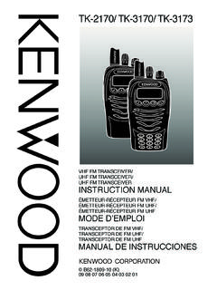
Transcription of INSTRUCTION MANUAL
1 B62-1228-20 (K,E,M)09 08 07 06 05 04 03 02 01 KENWOOD CORPORATIONINSTRUCTION MANUAL144/440 MHz FM DUAL BANDER144/430 MHz FM DUAL BANDERTM-D700 ATM-D700A144/430 MHz FM DUAL BANDERTM-D700 ETHANK YOU!We are grateful you decided to purchase thisKENWOOD FM transceiver. KENWOOD alwaysprovides Amateur Radio products which surprise andexcite serious hobbyists. This transceiver is noexception. This time KENWOOD presents a mobile witha built-in TNC to make data communications much moreconvenient than before. KENWOOD believes that thisproduct will satisfy your requirements on both voice anddata COVERED BY THIS MANUALThe models listed below are covered by this :144/440 MHz FM Dual Bander( Canada)TM-D700E:144/430 MHz FM Dual Bander(Europe)TM-D700A:144/430 MHz FM Dual Bander(General market)FEATURESThis transceiver has the following main features: Has a built-in TNC which conforms to the With a portable computer, allows you toenjoy Packet operation quite easily.
2 Includes a program for dealing with data formatssupported by Automatic Packet/ Position ReportingSystem (APRS ). Is capable of receiving packet data on one band whilereceiving audio on the other band. Enhanced Programmable Memory (PM) channelsstore virtually entire current operating environmentsfor your quick recall. Contains a total of 200 memory channels to programfrequencies and other various data. Allows eachmemory channel to be named using up to 8alphanumeric and special ASCII characters. Visual Scan graphically and simultaneously showsthe conditions of up to 181 frequency channels. Continuous Tone Coded Squelch System (CTCSS) orDigital Code Squelch (DCS) rejects unwanted callsfrom other stations. The separate front panel can be mounted in aconvenient different place from the main unit. Equipped with an easy-to-read large LCD withalphanumeric display capability.
3 Enhances the functions of an optional VC-H1 Interactive Visual Communicator designed forplug-and-play color slow-scan television (SSTV). Utilizes Sky Command System 2 designed to controla KENWOOD HF transceiver at a remote location( Canada only).iPRECAUTIONSP lease observe the following precautions to preventfire, personal injury, and transceiver damage: When operating mobile, do not attempt to configureyour transceiver while driving because it is simplytoo dangerous. Be aware of local laws pertaining to the use ofheadphones/headsets while driving on publicroads. If in doubt, do not wear headphones whilemobiling. Do not transmit with high output power forextended periods. The transceiver may overheat. Do not modify this transceiver unless instructed bythis MANUAL or by KENWOOD documentation. Do not expose the transceiver to long periods ofdirect sunlight nor place the transceiver close toheating appliances.
4 Do not place the transceiver in excessively dustyareas, humid areas, wet areas, nor on unstablesurfaces. If an abnormal odor or smoke is detected comingfrom the transceiver, turn OFF the powerimmediately. Contact a KENWOOD service stationor your dealer. The transceiver is designed for a V powersource. Never use a 24 V battery to power TO THE USEROne or more of the following statements may beapplicable:FCC WARNINGThis equipment generates or uses radio frequency energy. Changes ormodifications to this equipment may cause harmful interference unlessthe modifications are expressly approved in the INSTRUCTION MANUAL . Theuser could lose the authority to operate this equipment if an unauthorizedchange or modification is TO THE DIGITAL DEVICE USER REQUIRED BYTHE FCCThis equipment has been tested and found to comply with the limits for aClass B digital device, pursuant to Part 15 of the FCC Rules.
5 Theselimits are designed to provide reasonable protection against harmfulinterference in a residential equipment generates, uses and can generate radio frequencyenergy and, if not installed and used in accordance with the instructions,may cause harmful interference to radio communications. However,there is no guarantee that the interference will not occur in a particularinstallation. If this equipment does cause harmful interference to radio ortelevision reception, which can be determined by turning the equipmentoff and on, the user is encouraged to try to correct the interference byone or more of the following measures: Reorient or relocate the receiving antenna. Increase the separation between the equipment and receiver. Connect the equipment to an outlet on a circuit different from that towhich the receiver is connected. Consult the dealer for technical condensation occurs inside the transceiver:Condensation may occur inside the transceiver in such a case where theroom is warmed using a heater on cold days or where the transceiver isquickly moved from a cold room to a warm room.
6 When condensationoccurs, the microcomputer and/or the transmit/receive circuits maybecome unstable, resulting in transceiver malfunction. If this happens,turn OFF the transceiver and just wait for a while. When the condenseddroplets disappear, the transceiver will function BASICSSWITCHING POWER 19 ADJUSTING 19 SELECTING A 19 SELECTING A 20 ADJUSTING 21 Selecting Output 21 CHAPTER5 MENU SET-UPMENU 22 MENU 23 CHAPTER6 OPERATING THROUGH REPEATERSPROGRAMMING 29 Selecting Offset 29 Selecting Offset 29 Activating Tone 30 Selecting a Tone 30 AUTOMATIC REPEATER 31 TRANSMITTING A 1750 Hz 32 REVERSE 33 AUTOMATIC SIMPLEX CHECK (ASC).. 33 TONE FREQ. 34 CHAPTER7 MEMORY CHANNELSSIMPLEX & REPEATER OR ODD-SPLITMEMORY CHANNEL?.. 35 STORING SIMPLEX FREQUENCIES ORSTANDARD REPEATER 36 SUPPLIED 1 CONVENTIONS FOLLOWED IN THIS 1 CHAPTER1 PREPARATIONMOBILE 2 Main Unit 2 Front Panel 3 FIXED STATION 4 MODULAR PLUG CABLE 4DC POWER CABLE 5 Mobile 5 Fixed Station 6 Replacing 7 ANTENNA 7 ACCESSORY 8 External 8 CHAPTER2 YOUR FIRST QSOCHAPTER3 GETTING ACQUAINTEDFRONT 10 MAIN UNIT- 12 MAIN 12 MICROPHONE.
7 13 INDICATORS .. 14 BASIC TRANSCEIVER 15 BUTTON FUNCTION 16 BAND A & 17TX BAND AND CONTROL 17 MIC KEYPAD DIRECT ENTRY (MC-53DM ONLY) .. 18iii12345678910111213141516171819202122 PROGRAM 52 Setting Scan 52 Using Program 53 MHz 53 CALL/VFO 54 CALL/MEMORY 54 CHAPTER10 CONTINUOUS TONE CODED SQUELCHSYSTEM (CTCSS)USING 55 CTCSS FREQ. 56 CHAPTER11 DIGITAL CODE SQUELCH (DCS)USING 57 DCS CODE 58 CHAPTER12 DUAL TONE MULTI-FREQUENCY (DTMF)FUNCTIONS (WITH MC-53DM ONLY) MANUAL 59 DTMF 59 AUTOMATIC 60 Storing a DTMF Number in 60 Transmitting a Stored DTMF 61 Selecting TX 61 Selecting Pause 61 CHAPTER13 PROGRAMMABLE FUNCTION (PF) KEYSCHAPTER14 AUXILIARY FUNCTIONSDIRECT FREQUENCY ENTRY(WITH MC-53DM ONLY).. 63 CHANGING FREQUENCY STEP 64 PROGRAMMABLE 64 STORING ODD-SPLIT 36 RECALLING A MEMORY 37 CLEARING A MEMORY 37 NAMING A MEMORY 38 CALL 39 Recalling the Call 39 Reprogramming the Call 39 MEMORY-TO-VFO 40 CHANNEL 40 PARTIAL OR FULL RESET?
8 41 CHAPTER8 PROGRAMMABLE MEMORY (PM)PROGRAMMABLE 42 APPLICATION 43 STORING IN PM 44 RECALLING A PM 44 AUTO PM CHANNEL 45PM CHANNEL 45 CHAPTER9 SCANVISUAL 47 Selecting the Number of 47 Using Visual 48 SELECTING SCAN RESUME 49 VFO 50 MEMORY 50 Locking Out a Memory 51 GROUP 51ivCHAPTER16 WIRELESS REMOTE CONTROL( CANADA ONLY) 74 CONTROL 75 CHAPTER17 SKY COMMAND 22222 ( CANADA ONLY)CONNECTING THE TRANSPORTER WITHTHE HF 77 PREPARATION 78 PROGRAMMING CALL 79 PROGRAMMING A TONE 79 CONTROL 80 CHAPTER18 REPEATER FUNCTION( CANADA ONLY)CHAPTER19VS-3 VOICE SYNTHESIZER (OPTIONAL)CHAPTER20 OPTIONAL ACCESSORIESCHAPTER21 INSTALLING OPTIONSINSTALLING THE VS-3 VOICESYNTHESIZER 85 INSTALLING THE PG-4X EXTENSIONCABLE 85 CHAPTER22 MAINTENANCEGENERAL 87 SERVICE 88 SPECIFICATIONSINDEXDISPLAY 65 AUTO DIMMER 65 DISPLAY CONTRAST 65 POSITIVE/ NEGATIVE 65 BLANKING A BAND 66 AUTOMATIC BAND CHANGE ( ).
9 66 TRANSCEIVER 67 ALL-CONTROL 67 CHANGING MULTI-FUNCTIONBUTTON 67S-METER 68 Squelch Hang 68 CHANGING BEEP 69 KEY BEEP ON/ 69 SWITCHING FM/AM 69 ADVANCED INTERCEPT POINT (AIP).. 69 TIME-OUT TIMER (TOT).. 70 AUTOMATIC POWER OFF (APO).. 70 POWER-ON 71 DISPLAY 71 CHANGING SPEAKER 72 SPEAKER 72 CHANGING TX/RX DEVIATION (TM-D700E ONLY).. 72 CHAPTER15 MICROPHONE CONTROL (WITH MC-53DM ONLY)1 SUPPLIED ACCESSORIESA market area code (K, E, or M4) can be found on thelabel attached to the package screw set includes screws for attaching the microphonehanger {page 8}.2 See the separate MANUAL , SPECIALIZEDCOMMUNICATIONS {page 10}.3 See page FOLLOWED IN THIS MANUALThe writing conventions described below have beenfollowed to simplify instructions and avoid :K54-CM:4M/EXX-5160-19 TXX-6930-19T11elbacrewopCDXX-1112-03E1)A 51(esufreviecsnarTXX-7100-15F1tekcarbgni tnuomlenaptnorF)riapeno(XX-3660-92 JXX-4660-92J11tekcarbgnitnuomtinu-niaMXX -8260-92J1)ylnoK(regnahenohporciMXX-6251 -91J1tinuniamrofteswercSK14M/EXX-2830-99 NXX-1330-99N11lenaptnorfrofteswercSXX-41 02-99N1elbacgulpraludoMXX-1933-03E1)"01/ 1( )ylnoeporuE/adanaC/.
10 ( 1launamnoitcurtsnIniaMsnoitacinummoCdezi laicepSXX-8221-26 BXX-3721-26B11noitcurtsnIodottahWsserP]Y EK[. )s1(]YEK[. ]1 YEK[,]2 YEK[.sserP1 YEKesaeler,yliratnemom1 YEKsserpneht, )s1(]F[,]YEK[.dlohdnasserP]F[rodnoces1ro fsserpneht, ]2 YEK[+]1 YEK[.dlohdnasserP1 YEKsserpneht, +]YEK[ ,FFOrewopreviecsnarthtiWdlohdnaYEKehtNOn rutneht,gnisserpybrewopreviecsnart]RWP[. 21 PREPARATION2 Position the transceiver, then insert and tightenthe supplied hexagon SEMS screws and flatwashers. There are 2 screws and 2 washerssupplied for each side of the bracket. Double check that all hardware is tightened toprevent vehicle vibration from loosening the bracketor transceiver. Determine the appropriate angle of the main unit,using the 3 screw holes on the rear edge of eachbracket INSTALLATIONThis transceiver asks you to install the front panel andmain unit at separate positions.)