Transcription of INSTRUCTION MANUAL - CVS Controls
1 CVS Series DBQ and DBAQ Control Valves Introduction Contained in this MANUAL are installation instructions, maintenance and parts information for the CVS DBQ and DBAQ Control Valves. Refer to the appropriate manuals for instructions for the accompanying actuator, positioner and additional accessories. Only trained or experienced personnel should carry out the operation and installation of all pressure equipment. If you have any questions regarding the equipment, contact your CVS Controls representative. Applications and Features The CVS Series DBQ and DBAQ Control Valves are ideally suited for high pressure water and steam applications, providing excellent pressure and flow control.
2 This design may be utilized in both high pressure and high temperature control service. CVS Series DBQ is a globe style valve, while the CVS Series DBAQ is an angle style valve, which may be used in angle piping or self draining applications. Valve bodies are available in 1 or 2 inch sizes, with casted flanged connections, and ASME body ratings of Class 1500, or Class 2500. LCC, WCB and CF8M are standard body materials. Additional materials may be available upon request. Sour Service Capability Optional NACE MRO175/ISO 15156-2009 Flow Characteristic This designs flow characteristic is up through the seat ring and out through the cage.
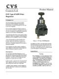
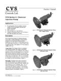
3 The CVS DBQ and DBAQ series valves are single port, metal seated valves. Figure 1: 2 CVS Series DBAQ INSTRUCTION MANUAL Head Office3900 101 Street Edmonton, Alberta T6E 0A5 CanadaOffice: (780) 437-3055 Fax: (780) 436-5461 Calgary Sales Office 3516 114 Avenue SE Calgary, Alberta T2Z 3V6 CanadaOffice: (403) 250-1416 Fax: (403) 291-9487 Website: Email: SPECIFICATIONS End Connection Style Flanged raised Face (RF) ASME Class 1500, or Class 2500 (ASME edition) Flanged Ring Type Joint (RTJ) ASME Class 1500, or Class 2500 (ASME edition) Maximum Inlet Pressure* Raised Face Flange Consistent with Class 1500 or Class 2500 per ASME edition Ring Type Joint Consistent with Class 1500 or Class 2500 per ASME edition Shutoff Classification Standard Class IV leakage of less than.
4 01% of maximum capacity, using air at 50 psid Optional Class V leakage of less than .0005cc per minute, per inch of port diameter per psid using water at service pressure drop Flow Direction Taper Plug and M-Form Trims Up through the seat ring and out through the cage Flow Characteristic Refer to Table 2. *Pressure and temperature limits in this MANUAL , and any applicable standard should not be exceededTable 2: Yoke Boss, Stem, Port, and Travel Specifications in inches (mm) Body Size Yoke Boss Diameter Stem Diameter Standard Cage and Seat Ring Combinations M-Form PlugTaper Plug Port Diameter Rated Travel Port Diameter Rated Travel 1 2-13/16* (71)3-9/16 (90) 5 (127)1/2* ( ) 3/4 ( ) 1, 1-1/4 ( , ) 1/4, 3/8, 1/2, 3/4, 1** ( , , , , ) 3/4 , 1** (19, 25) 3/4 ( ) 1 ( ) 3/4 * (19) 1 (25) 2 3-9/16* (90)5 (127)3/4* ( ) 1, 1-1/4 ( , ) 1/4, 3/8, 1/2, 3/4, 1, 1-1/4 ( , , , , , ) 3/4*, 1** (19, 25) 3/4, 1, 1-1/4 ( , , ) 1* (25) 1-1/8* (29)
5 *Standard Configuration**Not available in Class 2500 bodies **Flow Characteristic is slightly sacrificed Table 1: Specifications CVS Series DBAQ installation Exceeding the recommended pressure and temperature limits from Table 1, or those indicated on the nameplates of your CVS Controls Valve, can result in personal injury and property damage. CVS Controls recommends the installation of a relief valve to protect against overpressure situations. CVS Series DBQ and DBAQ are designed to meet specific conditions for fluid control, temperature, pressure and pressure drop. The limiting factor on these valves can be the body/trim material combinations.
6 Do not install these valves in any other applications without first consulting with your CVS Controls representative. 1. Inspect the valves for shipping damage and foreign debris while uncrating. 2. Ensure the pipeline is free from welding slag, chips and other debris by blowing out the line before installation . 3. Position the valve on the line so the flow direction indicator corresponds to the direction of the flow of the pipeline. 4. CVS Controls recommends the installation of a standard three-valve maintenance bypass. This will allow the isolation of the control valve without shutting down the pipeline system.
7 5. Install approved gaskets between the valve body and the pipeline flanges. 6. If the actuator has been shipped separately, refer to the mounting procedure in the applicable INSTRUCTION MANUAL . 7. If the valve body arrives without packing installed in the packing box, it will be necessary to install the packing before putting the valve into service. To complete these procedures, follow the instructions under packing maintenance in this MANUAL . 8. *Note: It may be necessary to adjust the packing to prevent leakage. Prior to shipping the packing was tightened, and may require some adjustment for specific conditions.
8 MAINTENANCE Internal valve components are subject to normal deterioration and must be inspected and replaced as required. The necessity of inspections and replacement of parts will depend on the severity of service conditions. Inspections and maintenance must be carried out on a regularly scheduled basis. To ensure the safety of personnel and to protect against property damage, the following steps should be carried out before beginning disassembly. 1. To prevent the valve from opening suddenly, disconnect any operating lines to the actuator. This would include air pressure, electrical power or control signal lines.
9 2. Isolate the valve by using the bypass valve, or by shutting down the process completely. Relieve the pressure and drain the process fluid from both sides of the valve. 3. Relieve the pressure contained in the actuator by venting the actuator loading pressure and relieving any power actuator spring compression. 4. Lock-out procedures should be strictly adhered to while the equipment is being serviced. 5. To ensure a good gasket seal, the gasket should be replaced upon re-assembly whenever it becomes disturbed by removing or shifting gasketed parts. PACKING LUBRICATION These instructions are for the lubricator or lubricator isolation valve (Figure 2).
10 If the lubricator or lubricator isolation valve have been installed, they will be in place of the pipe plug and are designed for packing that requires lubrication, including PTFE composition. CVS Controls recommends a silicone based lubricant. Lubricant is not recommended for oxygen services or for processes that operate in excess of 500F (260oC). To add lubricant to the packing box, turn the capscrew in a clockwise direction. For Lubricator/Isolating Valve 1. Open the isolating valve. 2. Turn the capscrew in a clockwise direction. 3. Close the isolating valve. PACKING LEAKAGE Spring-Loaded PTFE V-Ring Packing To eliminate leakage, tighten the packing flange nuts (key 18, figure 7).