Transcription of Instruction Manual: Fisher 3582 and 3582i …
1 Instruction Manual 3582, 582i , and 3583. D200138X012 August 2017. Fisher 3582 and 3582i Positioners, 582i electro pneumatic Converter, and 3583 Valve Stem position Transmitter Contents Changing Cam position .. Pressure Connections .. 18. 18. Introduction .. 2 Supply Connection .. 18. Scope of Manual .. 2 Output Connection .. 20. Description .. 2 Instrument Connection .. 20. Type Number Descriptions .. 6 Diagnostic Connections .. 20. Specifications .. 7 Vent .. 21. Educational Services .. 7 Electrical Connections for 3582i Installation .. 7 Valve positioner .. 21. Hazardous Area Classifications and Special 582i Converter Installation .. 23. Instructions for Safe Use and Installation Operating Information.
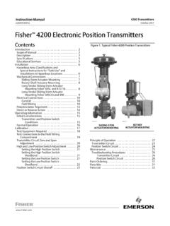
2 24. in Hazardous Areas for 582i Converter .. 8 Valve positioner Cam Information .. 24. CSA .. 9 Valve Stem position Transmitter Cam FM .. 10 Information .. 26. ATEX .. 10. (continued on page 2). IECEx .. 12. Mounting .. 13. Figure 1. Typical Mounting for Fisher 3582 and 3582i Positioners and 3583 Transmitters W5498 1 W8424 W5499 1. CONTROL VALVE WITH CONTROL VALVE WITH CONTROL VALVE WITH. 3582 positioner 3582i positioner 3583 TRANSMITTER. 3582, 582i , and 3583 Instruction Manual August 2017 D200138X012. Contents (cont'd) Maintenance .. Changing the Range Spring .. 35. 36. Valve positioner Bypass Operation .. 26 Replacing Gaskets .. 36. Input Signal Ranges .. 27 Replacing the Nozzle O Ring.
3 37. Valve positioner Split Range Operation .. 27 Replacing the Relay .. 37. Changing Valve positioner Action .. 28 Adjusting the Flapper Pivot .. 38. Changing Valve Stem position Transmitter Replacing the 582i Converter Action .. 28 Primary O Ring and Filter .. 38. Calibration Of Valve positioner Or Replacing the 582i Converter Housing Valve Stem position Transmitter .. 29 Cap O Ring .. 38. Beam Alignment .. 29 Removing the 582i Converter .. 38. Calibration .. 31 Reassembling the 582i Converter .. 39. Principle of Operation .. 32 Parts Ordering .. 40. 3582 Valve Positioners .. 32 Parts Kits .. 40. 3582i Valve positioner .. 33 Parts List .. 41. 3583 Valve Stem position Transmitters.
4 34 Loop Schematics .. 54. Introduction Scope of Manual This Instruction manual includes installation, operation, calibration, maintenance, and parts ordering information for Fisher 3582 pneumatic valve positioners, the 3582i electro pneumatic valve positioner , and 3583 pneumatic valve stem position transmitters. Refer to separate Instruction manuals for information on the control valve, actuator, and accessories. Do not install, operate or maintain a 3582 pneumatic valve positioner , a 3582i electro pneumatic valve positioner , or a 3583 pneumatic valve stem position transmitter without being fully trained and qualified in valve, actuator and accessory installation, operation and maintenance.
5 To avoid personal injury or property damage it is important to carefully read, understand, and follow all of the contents of this manual, including all safety cautions and warnings. If you have any questions about these instructions, contact your Emerson sales office or Local Business Partner before proceeding. Description 3582 pneumatic valve positioners and the 3582i electro pneumatic valve positioner shown in figure 1 are used with diaphragm actuated, sliding stem control valve assemblies. The pneumatic valve positioners receive a pneumatic input signal from a control device and modulate the supply pressure to the control valve actuator. The positioner adjusts the actuator supply pressure to maintain a valve stem position proportional to the pneumatic input signal.
6 3582NS positioners are designed for nuclear power applications. The 3582NS construction includes materials that provide superior performance at elevated temperature and radiation levels. The O rings are EPDM (ethylene propylene) and the diaphragms are EPDM/meta aramid fabric. EPDM demonstrates superior temperature capability and shelf life over nitrile. The meta aramid diaphragm fabric demonstrates improved strength retention at elevated temperature and radiation conditions. CAUTION. Use a clean, dry, oil free air supply with instruments containing EPDM components. EPDM is subject to degradation when exposed to petroleum based lubricants. 2. Instruction Manual 3582, 582i , and 3583.
7 D200138X012 August 2017. Table 1. Specifications for Fisher 3582 and 3582i Valve Positioners Note: Specifications for 3582 positioners include Maximum Steady State Air Consumption(2). 3582A, 3582C, 3582D, 3582G, and 3582NS unless 3582. otherwise indicated bar (20 psig) Supply: normal m3/hr ( scfh). bar (30 psig) Supply: normal m3/hr ( scfh). Input Signal bar (35 psig) Supply: normal m3/hr ( scfh). 3582: 3582i J to bar (3 to 15 psig), J to bar bar (20 psig) Supply: normal m3/hr ( scfh). (6 to 30 psig), or J split range, see table 10 bar (30 psig) Supply: normal m3/hr ( scfh). 3582i : bar (35 psig) Supply: normal m3/hr ( scfh). 4 to 20 mA DC constant current with 30 VDC. maximum compliance voltage, can be split range, see Maximum Supply Air Demand table 10 bar (20 psig) Supply: normal m3/hr ( scfh).
8 Bar (30 psig) Supply: normal m3/hr ( scfh). Equivalent Circuit for 3582i bar (35 psig) Supply: normal m3/hr ( scfh). The 582i converter equivalent circuit is 120 ohms, shunted by three volt zener diodes (see figure 10) Performance 3582. Output Signal Independent Linearity: 1 percent of output signal Type: pneumatic pressure as required by actuator up span to 95 percent of maximum supply Hysteresis: percent of span Action: Field reversible between J direct and 3582i J reverse within the pneumatic valve positioner Independent Linearity: 2 percent of output signal span Supply Pressure(1) Hysteresis: percent of span Recommended: bar (5 psi) above actuator Electromagnetic Compatibility for 582i requirement electro pneumatic converter Maximum: bar (50 psig) or pressure rating of Meets EN 61326 1:2013.
9 Actuator, whichever is lower Immunity Industrial locations per Table 2 of the EN 61326 1 standard. Performance is Supply Medium: Air or Natural Gas shown in table 3 below. Supply medium must be clean, dry, and noncorrosive Emissions Class A. Per ISA Standard ISM equipment rating: Group 1, Class A. A maximum 40 micrometer particle size in the air Note: The electromagnetic compatibility system is acceptable. Further filtration down to 5 specifications also apply to the 3582i micrometer particle size is recommended. Lubricant 3582 and 3582i content is not to exceed 1 ppm weight (w/w) or Typical Open Loop Gain (Output Signal): volume (v/v) basis. Condensation in the air supply J 100 in the range of to bar (3 to 15 psig).
10 Should be minimized J 55 in the range of to bar (6 to 30 psig). Per ISO 8573-1. 3582 and 3582i Maximum particle density size: Class 7. Typical Open Loop Gain (Output Signal): Oil content: Class 3. J 100 in the range of to bar (3 to 15 psig). Pressure Dew Point: Class 3 or at least 10_C less than J 55 in the range of to bar (6 to 30 psig). the lowest ambient temperature expected Note: The 3582i is not approved for use with natural Operating Influences gas as the supply medium Supply Pressure 3582: Valve travel changes less than percent per bar ( percent per 2 psi) change Input Bellows Pressure Rating(1) in supply pressure See table 9 for minimum and maximum pressure Supply Pressure 3582i : Valve travel changes less ratings (allowable input signal) for each available than percent per bar ( percent per 2 psi).