Transcription of Instructions - Det-Tronics
1 Instructions Duct Mount Accessory Q5016. Rev: 11/16 95-8752. Table of Contents DESCRIPTION .. 1 INLET AND OUTLET TUBES .. 7. FEATURES .. 1 ASSEMBLING THE MONITORING CHAMBER .. 8. OPERATION .. 1 AIR FLOW MONITORING .. 9. SPECIFICATIONS .. 2. MAINTENANCE .. 9. INSTALLATION .. 2. DEVICE REPAIR AND RETURN .. 9. Detector Location .. 2 Tools for Assembly .. 4 Tools for Detector Test .. 4 ORDERING INFORMATION .. 10. Q5016 PANEL ASSEMBLY MOUNTING .. 4 SPARE PARTS .. 10. Spare Parts List .. 10. MOUNTING THE DETECTOR .. 6. 2 95-8752. Instructions . DESCRIPTION Duct Mount Accessory The Detector Electronics Model Q5016 Duct Mount Q5016.
2 Accessory is used with the Model U5015 Det- Tronics SmokeWatch Explosion Proof smoke Detector to detect smoke within air handling duct work. Mounted to the exterior of the duct wall, the Q5016 utilizes the differential pressure created between the inlet (sampling) and outlet (exhaust). tubes to drive a continuous air sample through the SmokeWatch measurement chamber. The Q5016. is provided with all necessary tubes and fittings to enable proper operation with a model U5015. SmokeWatch smoke detector (sold separately). The Q5016 is designed for hazardous industrial and commercial applications. FEATURES. Rugged design for environmental extremes Designed to operate effectively with smoldering and rapidly growing fires The length of the inlet tube is determined by the Has the ability to annunciate fault, ensuring no width of the duct to be monitored.
3 The inlet tube undisclosed failures should span the entire width of the duct. Select Works with a small volume of air the shortest inlet tube that exceeds the width of the duct to be protected. It can then be cut to Designed to meet UL268A. the exact length during installation. Can be installed horizontally or vertically OPERATION Inlet tubes are .92 inch (.28 cm) outside diameter, and are notched on one end to enable proper The Q5016 is an accessory that is used with the installation into the access ports on the Q5016. Det-Tronics U5015 SmokeWatch to provide smoke mounting plate. The inlet tube includes small detection monitoring within duct work.
4 Duct air pre-drilled inlet holes, which must be aligned to velocity drives a cross-duct air sample into the face directly into the airflow (upstream) in order upstream sample inlet tube, which in turn routes to capture airflow and generate proper differential the air sample into the detector. The downstream pressure. Tubes are compression-fit into the body. air sample outlet tube returns the air sample back A stop plug is provided for the end of the inlet into the duct. The critical parameter for proper tube to ensure that all airflow is directed towards operation of the Q5016 is that all sample tubing connections and duct penetrations must be the SmokeWatch detector.
5 Completely sealed and without any leakage. The mounting plate is provided with an NBR sheet The Q5016 smoke Duct Accessory works gasket to ensure a proper seal on flat mounting exclusively with the U5015 SmokeWatch smoke surfaces. detector. For information on the operation, wiring and alarm of the U5015 smoke detector, please One inlet tube and one outlet tube are furnished reference manual number 95-8723. with each accessory. Outlet tubes are 1 foot ( meters) in length. The length of the inlet tube must be specified at the time of order and are available for ducts in the following widths: 1, 3, 6, or 9 feet ( , , , or meters).
6 1. Detector Electronics Corporation 2016 Rev: 11/16 95-8752. SPECIFICATIONS ACCESSORY SHIPPING WEIGHTS . Box 1 (Includes Q5016 Duct Accessory + one 1. MATERIALS: ft outlet tube + box + instruction manual). BODY Box 2 (Includes inlet tube in Aluminum, 6000 series. shipping container). Finish: MIL-DTL-5541 Type II Class 1A. Box 1 = lbs. ( kg). Box 2 = Will vary depending on the tube length SAMPLING TUBES . and number of tubes. Galvanized steel tubing .92 inch ( cm) dia. Inlet tube: available for 1, 3, 6, or 9 foot ( , , or Individual Tube Weight: meter) wide ducts. 1 ft = lbs. 3 ft = lbs. Outlet Tube: 1 foot ( meter) standard length tube.
7 6 ft = lbs. 9 ft 8 in = lbs. FASTENERS . Stainless steel. TOTAL INSTALLED WEIGHTS . Includes Q5016 Duct Accessory + one outlet DIMENSIONS tube + one 3 ft. inlet tube + one U5015, 2-port Refer to Figure 1. model. AIR VELOCITY RANGE Q5016 -1 / U5015 = lbs. ( kg). 300 to 4000 ft/min ( to meters/min). Q5016-3 / U5015 = lbs. ( kg). INGRESS PROTECTION Q5016-6 / U5015 = lbs. ( kg). Designed to meet NEMA 250 requirements for type 4X ( Det-Tronics verified). Q5016-010 / U5015 = lbs. ( kg). ( ). ( ) INSTALLATION. The Q5016 Air Duct smoke Detector accessory mounts externally on any duct wall with the air inlet (sample) and outlet (exhaust) air tubes extending into the duct to provide a continuous cross sectional sampling of the air moving through the air handling system.
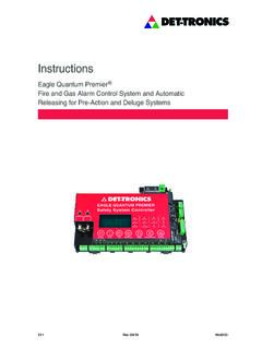
8 DETECTOR LOCATION. ( ) Detectors can be mounted in the supply system downstream of the filters, or in the return system at the point of entry into a common return duct (Figure 2). Whenever possible, detectors that are mounted on a return duct should be at a distance A2700 INLET DIRECTION equivalent to six duct widths from any duct openings, sharp bends, branch connections, or deflection plates. For additional information regarding the location and spacing of duct smoke detectors, refer to the National Fire Protection OUTLET Association (NFPA) Standard 90A, Installation DIRECTION. of Air Conditioning and Ventilation Systems and NFPA Standard 72 for Automatic Fire Detectors.
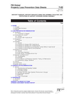
9 Figure 1 Q5016 Dimensions in Inches (cm). 2 95-8752. STOP PLUG. DUCT WALL. DIRECTION OF AIR FLOW. STOP PLUG. DUCT WALL. DIRECTION OF AIR FLOW. A2707. Figure 2 Tube position and orientation 3 95-8752. Tools Required for Assembly and Mounting: Q5016 PANEL ASSEMBLY MOUNTING. 1/2 inch Box End, Socket, or Crescent Wrench 3/16 inch Hex Key 1. The Q5016 duct accessory should be 3/8 inch Hex Key installed in an easily accessible location 1-3/8 inch Open End, or Crescent Wrench approximately six ducts widths from bends, Drill duct openings, or deflection plates (see Drill bits -11/32 inch and 1-5/16 inch Figure 3). These locations provide fairly Center punch uniform, non-turbulent air flow.
10 If no access Hammer panel is present at the desired mounting Panel mounting template (included) location, an access opening will need to be Access panel kit (if required) created above or adjacent to the installation point to facilitate attachment of the Q5016 to Tools Required for Detector Test: the duct wall. Calibrated manometer capable of measuring NOTE. - inches ( to mm) of H2O To ensure proper operation of the sampling Differential pressure adaptors 013655-001 tubes, observe proper inlet and outlet tube position and orientation as illustrated in Components for the Q5016 Accessory will arrive Figure 2.