Transcription of Integrated Digital Audio Interface Receiver and ...
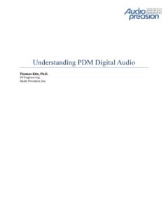
1 S/PDIFINDIX4192 DSPx4S/PDIFOUTPCM x1 GPO/INTI2Cx1 PCM5242 PCM x1 TPA6120A2 ProductFolderSample &BuyTechnicalDocumentsTools &SoftwareSupport &CommunityAn IMPORTANTNOTICEat the end of this datasheetaddressesavailability,warranty, changes,use in safety-criticalapplications,intellectual propertymattersand FEBRUARY2006 REVISEDSEPTEMBER2016 DIX4192 IntegratedDigitalAudioInterfaceReceivera nd Transmitter11 Features1 DigitalAudioInterfaceTransmitter(DIT) SupportsSamplingRatesUp to 216 kHz IncludesDifferentialLine DriverandCMOS-BufferedOutputs DigitalAudioInterfaceReceiver(DIR) PLL LockRangeIncludesSamplingRatesfrom20 kHz to 216 kHz FourDifferential-InputLine Receiversand anInputMultiplexer BypassMultiplexerRoutesLine ReceiverOutputsto Line Driverand BufferOutputs AutomaticDetectionof Non-PCMA udioStreams(DTSCD/LDand IEC 61937formats) AudioCD Q-ChannelSub-CodeDecodingandDataBuffer Low JitterRecoveredClockOutput User-SelectableSerialHostInterface.
2 SPI orI2C ProvidesAccessto On-ChipRegistersandDataBuffers StatusRegistersand InterruptGenerationforFlagand ErrorConditions Block-SizedDataBuffersfor BothChannelStatusand UserData Two AudioSerialPorts(PortsA and B) SynchronousSerialInterfaceto ExternalSignalProcessors,DataConverters, and Logic Slaveor MasterModeOperationWithSamplingRatesUp to 216 kHz SupportsLeft-Justified,Right-Justified,a ndPhilipsI2S DataFormats SupportsAudioDataWordLengthsUp to24 Bits FourGeneral-PurposeDigitalOutputs MultifunctionProgrammableThroughControlR egisters ExtensivePower-DownSupport FunctionalBlocksMay Be DisabledIndividuallyWhenNot In Use PowerSupplies SmallTQFP-48 Package,CompatibleWiththeSRC4382and SRC43922 Applications DigitalAudioRecordersand MixingDesks DigitalAudioInterfacesfor Computers DigitalAudioRoutersand DistributionSystems BroadcastStudioEquipment DVDand CD Recorders SurroundSoundDecodersand A/V Receivers Car AudioSystems3 DescriptionTheDIX4192deviceis a highly-integratedCMOS devicedesignedforusein digitalaudiointerfacereceiver(DIR)andtra nsmitter(DIT),two audioserialports,and flexibledistributionlogicfor interconnectionof the functionblockdataand compatiblewiththe AES3,S/PDIF,IEC60958, DIT maybeoperatedat samplingratesup to 216 DIRlockrangeincludessamplingratesfrom20 kHzto216 (1)PARTNUMBERPACKAGEBODYSIZE(NOM)DIX4192 TQFP(48) (1) For all availablepackages,see the orderableaddendumatthe end of the FEBRUARY2006.
3 DIX4192 SubmitDocumentationFeedbackCopyright 2006 2016,TexasInstrumentsIncorporatedTableof Contents1 Description(continued)..36 Pin Configurationand Applicationand Deviceand Mechanical,Packaging,and RevisionHistoryNOTE:Pagenumbersfor previousrevisionsmay differfrompagenumbersin the (April2016)to RevisionFPage ChangedfMCLKMax : (January2016)to RevisionEPage Changed"IIHHigh-levelinputcurrent" MAXvalueFrom:10 A To: 25 A in ChangedByte2 in Figure22a) CurrentAddressRead,..25 ChangesfromRevisionC (June2006)to RevisionDPage AddedESDR atingstable,FeatureDescriptionsection,De viceFunctionalModessection,Applicationan dImplementationsection,PowerSupplyRecomm endationssection,Layoutsection,Deviceand DocumentationSupportsection,andMechanica l,Packaging,and FEBRUARY2006 REVISEDSEPTEMBER2016 ProductFolderLinks.
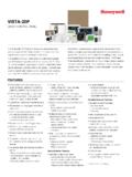
4 DIX4192 SubmitDocumentationFeedbackCopyright 2006 2016,TexasInstrumentsIncorporated5 Description(continued)The DIX4192deviceis configuredusingon-chipcontrolregistersan d databuffers,whichare accessedthrougheithera 4-wireserialperipheralinterface(SPI)port ,or a 2-wirePhilipsI2C bus a varietyof flag and errorbits,whichare derivedfromthe open-draininterruptoutputpin is provided,and is supportedby flexibleinterruptreportingand masterresetinputpin is providedfor initializationby a hostprocessoror DIX4192devicerequiresa ,in additionto a poweringportionsof theDIR,DIT,and line driverand separatelogicI/O V, providingcompatibilitywith low voltagelogicinterfacestypicallyfoundon DIX4192deviceis availablein a lead-free,TQFP-48package,and is pin- andregister-compatiblewith the TexasInstrumentsSRC4382and V IOMULTI-CHPCMADCPCMPORTSS/PDIFPORTSDIX41 92 YesNoNo24 differentialLine IN and 1differentialLine OutPCM9211 NoYesYesUp to 3 IN and up to 3 OutUp to 12 single-endedINand up to 2 single-endedOutDIX9211 NoYesNoUp to 3 IN and up to 3 OutUp to 12 single-endedINand up to 2 single-endedOut363534333231302928272625 SYNCBLSAESOUTVDD33TX+TX-DGND2 GPO4 GPO3 GPO2 GPO1 MCLKBCKBLRCKBSDINBSDOUTBBGNDDGND3 VIONCSDOUTASDINALRCKABCKARXCKINCNCDGND1 VDD18 CPMCS/A0 CCLK/SCLCDIN/A1 CDOUT/SDAINTRST123456789101112RX1+RX1-RX 2+RX2-RX3+RX3-RX4+RX4-VCCAGNDLOCKRXCKO48 47 46 45 44 43 42 41 40 39 3813 14 15 16 17 18 19 20 21 22 2337244 DIX4192 SBFS031F FEBRUARY2006.
5 DIX4192 SubmitDocumentationFeedbackCopyright 2006 2016,TexasInstrumentsIncorporated(1)I = Input,O = Output,PWR= Power,GND= Ground7 Pin Configurationand FunctionsPFBP ackage48-PinTQFPTop ViewPin FunctionsPINTYPE(1) bufferedAES3-encodeddataAGND10 GNDDIR comparatorand PLL power-supplygroundBCKA37I/OAudioserialPo rt A bit clockBCKB48I/OAudioserialPort B bit clockBGND44 GNDS ubstrateground,connectto AGND(pin 10)BLS35I/ODIT blockstartclockCCLKor SCL20 ISerialdataclockfor SPI modeor I2C modeCDINor A121 ISPI port serialdatainputor programmableslaveaddressfor I2C modeCDOUTor SDA22I/OSPI port serialdataoutput(tri-stateoutput)or serialdataI/O for I2C modeCPM18 IControlport mode,0 = SPI mode,1 = I2C modeCS or A019 IChipselect(activelow) for SPI modeor programmableslaveaddressfor I2C modeDGND116 GNDD igitalcoregroundDGND230 GNDDIR line receiverbias and DIT line driverdigitalgroundDGND343 GNDL ogicI/O FEBRUARY2006 REVISEDSEPTEMBER2016 ProductFolderLinks.
6 DIX4192 SubmitDocumentationFeedbackCopyright 2006 2016,TexasInstrumentsIncorporatedPin Functions(continued)PINTYPE(1) (open-drain,activelow)LOCK11 ODIR PLL lock flag (activelow)LRCKA38I/OAudioserialPort A Left/RightclockLRCKB47I/OAudioserialPort B left/rightclockMCLK25 IMasterclockNC14, 15, 41 No internalsignalconnection,internallybonde dto ESDpadRST24 IReset(activelow)RX1+1 ILine receiver1, noninvertinginputRX1 2 ILine receiver1, invertinginputRX2+3 ILine receiver2, noninvertinginputRX2 4 ILine receiver2, invertinginputRX3+5 ILine receiver3, noninvertinginputRX3 6 ILine receiver3, invertinginputRX4+7 ILine receiver4, noninvertinginputRX4 8 ILine receiver4, invertinginputRXCKI13 IDIR referenceclockRXCKO12 ODIR recoveredmasterclock(tri-stateoutput)SDI NA39 IAudioserialPort A datainputSDINB46 IAudioserialPort B datainputSDOUTA40 OAudioserialPort A dataoutputSDOUTB45 OAudioserialPort B dataoutputSYNC36 ODIT internalsyncclockTX+32 ODIT line drivernoninvertingoutputTX 31 ODIT line driverinvertingoutputVCC9 PWRDIR comparatorand PLL powersupply, , line receiverbias and DIT line driversupply, supply, to V(1)StressesbeyondthoselistedunderAbsolu teMaximumRatingsmay causepermanentdamageto the stressratingsonly,whichdo not implyfunctionaloperationof the deviceat theseor any otherconditionsbeyondthoseindicatedunder RecommendedOperatingProcedures.
7 Exposureto absolute-maximum-ratedconditionsfor extendedperiodsmay (unlessotherwisenoted)(1)MINMAXUNITP owersupplyVDD18 :digitallogicRXCKI,CPM,CS, CCLK,CDIN,CDOUT,INT, RST,MCLK,BLS,SYNC,BCKA,BCKB,LRCKA,LRCKB, SDINA,SDINB (VIO+ )VLine receiverinputvoltage(per pin)RX1+,RX1 , RX2+,RX2 , RX3+,RX3 , RX4+,RX4 (VDD33+ )VPPI nputcurrent(all pins exceptpowerand ground) 10mAAmbientoperatingtemperature 4085 CStoragetemperature,Tstg 65150 C6 DIX4192 SBFS031F FEBRUARY2006 :DIX4192 SubmitDocumentationFeedbackCopyright 2006 2016,TexasInstrumentsIncorporated(1)JEDE C documentJEP155statesthat 500-VHBM allowssafe manufacturingwith a standardESDcontrolprocess.(2)JEDEC documentJEP157statesthat 250-VCDM allowssafe manufacturingwith a (ESD)ElectrostaticdischargeHuman-bodymod el(HBM),per ANSI/ESDA/JEDECJS-001(1) 2500 VCharged-devicemodel(CDM),per JEDEC specificationJESD22-C101(2) (unlessotherwisenoted) (1)For moreinformationabouttraditionaland new thermalmetrics,see theSemiconductorand IC PackageThermalMetricsapplicationreport, (1)DIX4192 UNITPFB(TQFP)48 PINSR C/WR JC(top)Junction-to-case(top) C/WR C/W C/W specificationsare at TA= 25 C, VDD18= V, VDD33= V, VIO = V, and VCC= V, CHARACTERISTICS(ALLI/O PINSEXCEPTLINERECEIVERSANDLINEDRIVER) VIOVIIHHigh-levelinputcurrentIO= 4 mA, MUTE,SDINA,and AIO= 4 mA, all 4 VIOVCINI nputcapacitance3pFLINERECEIVERINPUTS(RX1 +,RX1 , RX2+,RX2 , RX3+,RX3 , RX4+,RX4 )
8 VTHD ifferentialinputsensitivityVoltageacross a givendifferentialinputpair150200mVVHYI nputhysteresis150mVLINEDRIVEROUTPUTS(TX+ ,TX )VTXOD ifferentialoutputvoltageRL= 110 AcrossTX+ and TX (MCLK) (MCLK)duty cycle45%55%DIGITALAUDIOINTERFACERECEIVER (DIR)PLL lock rangeTA= 25 C20216kHzfRXCKIR eferenceclockinput(RXCKI) (RXCKI)duty cycle45%55%fRXCKOR ecoveredclockoutput(RXCKO) FEBRUARY2006 REVISEDSEPTEMBER2016 ProductFolderLinks:DIX4192 SubmitDocumentationFeedbackCopyright 2006 2016,TexasInstrumentsIncorporatedElectri calCharacteristics(continued)All specificationsare at TA= 25 C, VDD18= V, VDD33= V, VIO = V, and VCC= V, (1)The typicalVIO supplycurrentis measuredusingthe DIX4192 EVMevaluationmodulewith loadingfromthe supplycurrentis dependentuponthe loadingon the (RXCKO)duty cycle45%55%Recoveredclockoutput(RXCKO)in trinsicjitterMeasuredcycle-to-cycle250ps RMSDIGITALAUDIOINTERFACETRANSMITTER(DIT) IntrinsicoutputjitterMeasuredcycle-to-cy cle200ps RMSPOWERSUPPLIESS upplycurrent:initialstartupAll blockspowereddownby defaultIDD18 SVDD18= V10 AIDD33 SVDD33= V10 AIIOSVIO = V300 AICCSVCC= V10 ASupplycurrent:quiescentAll blockspoweredup with no clocksappliedIDD18 QVDD18= =.
9 DynamicAll blockspoweredup, fS= 48 kHzIDD18 DVDD18= (1)VIO = V46mAICCDVCC= :high samplingrateAll blockspoweredup, fS= 192 kHzIDD18 HVDD18= V15mAIIOH(1)VIO = V47mAICCHVCC= :initialstartupAll blockspowereddownby default1mWTotalpowerdissipation:quiescen tAll blockspoweredup with no clocksapplied28mWTotalpowerdissipation:d ynamicAll blockspoweredup, fS= 48 kHz233mWTotalpowerdissipation:high samplingrateAll blockspoweredup, fS= 192 (PORTA ANDPORTB)fLRCKLRCK clockfrequency0216kHztLRCKDLRCK clockduty cycle50% pulsewidth10nstBCKLBCKlow pulsewidth10nstAISA udiodataInput(SDIN)set-uptime10nstAISHA udiodatainput(SDIN)hold time10nstADDA udiodataoutput(SDOUT)delay10nsHOSTINTERF ACE:SPI MODEfCCLKS erialclock(CCLK)frequency040 MHztCSCRCS fallingto CCLK rising8nstCFCSCCLK fallingto CS rising7nstCDSCDIN dataset-uptime7ns8 DIX4192 SBFS031F FEBRUARY2006 :DIX4192 SubmitDocumentationFeedbackCopyright 2006 2016,TexasInstrumentsIncorporatedTimingR equirements(continued)MINNOMMAXUNIT(1)Al l valuesreferredto the VIHminimumand VILmaximumlevelslistedin the DigitalI/O Characteristicssectionof this table.
10 (2)A devicemustinternallyprovidea hold time of at least300 ns for the SDAsignal(referredto the VIHminimuminputlevel)to bridgetheundefinedregionof the fallingedgeof SCL.(3)The maximumtHDDAThas only to be met if the devicedoesnot stretchthe Low period(tLOW) of the SCLsignal.(4)A FastmodeI2C bus devicecan be usedin a StandardmodeI2C bus system,but the requirementthat tSUDATbe 250 ns (minimum)mustthenbe the DIX4192,this conditionis automaticallythe case,becausethe devicedoesnot stretchthe Low periodof theSCLsignal.(5)CBis definedas the total capacitanceof one bus line in picofarads(pF).If mixedwith High-Speedmodedevices,fasterfall time6nstCFDOCCLK fallingto CDOUT datavalid3nstCSZCS risingto CDOUT high-impedance,3nsHOSTINTERFACE:I2C STANDARDMODE(1)fSCLSCL clockfrequency0100kHztHDSTAH oldtime repeatedSTART condition4 stLOWLow periodof stHIGHH ighperiodof SCLclock4 stSUSTASet-uptime stHDDATD atahold time0(2) (3) stSUDATD ataset-uptime250nstRRisetime for bothSDAand SDL1000nstFFall time for bothSDAand SDL300nstSUSTOSet-uptime for STOP condition4 stBUFBus free time betweenSTARTand sCBCapacitiveload for eachbus line400pFVNLN oisemarginat low level(includinghysteresis) VIOVVNHN oisemarginat high level(includinghysteresis) VIOVHOSTINTERFACE.