Transcription of Integrated Digital Audio Interface Receiver and ...
1 S/PDIFINDIX4192 DSPx4S/PDIFOUTPCM x1 GPO/INTI2Cx1 PCM5242 PCM x1 TPA6120A2 ProductFolderSample &BuyTechnicalDocumentsTools &SoftwareSupport &CommunityAn IMPORTANTNOTICEat the end of this datasheetaddressesavailability,warranty, changes,use in safety-criticalapplications,intellectual propertymattersand FEBRUARY2006 REVISEDSEPTEMBER2016 DIX4192 IntegratedDigitalAudioInterfaceReceivera nd Transmitter11 Features1 DigitalAudioInterfaceTransmitter(DIT) SupportsSamplingRatesUp to 216 kHz IncludesDifferentialLine DriverandCMOS-BufferedOutputs DigitalAudioInterfaceReceiver(DIR) PLL LockRangeIncludesSamplingRatesfrom20 kHz to 216 kHz FourDifferential-InputLine Receiversand anInputMultiplexer BypassMultiplexerRoutesLine ReceiverOutputsto Line Driverand BufferOutputs AutomaticDetectionof Non-PCMA udioStreams(DTSCD/LDand IEC 61937formats) AudioCD Q-ChannelSub-CodeDecodingandDataBuffer Low JitterRecoveredClockOutput User-SelectableSerialHostInterface.
2 SPI orI2C ProvidesAccessto On-ChipRegistersandDataBuffers StatusRegistersand InterruptGenerationforFlagand ErrorConditions Block-SizedDataBuffersfor BothChannelStatusand UserData Two AudioSerialPorts(PortsA and B) SynchronousSerialInterfaceto ExternalSignalProcessors,DataConverters, and Logic Slaveor MasterModeOperationWithSamplingRatesUp to 216 kHz SupportsLeft-Justified,Right-Justified,a ndPhilipsI2S DataFormats SupportsAudioDataWordLengthsUp to24 Bits FourGeneral-PurposeDigitalOutputs MultifunctionProgrammableThroughControlR egisters ExtensivePower-DownSupport FunctionalBlocksMay Be DisabledIndividuallyWhenNot In Use PowerSupplies SmallTQFP-48 Package,CompatibleWiththeSRC4382and SRC43922 Applications DigitalAudioRecordersand MixingDesks DigitalAudioInterfacesfor Computers DigitalAudioRoutersand DistributionSystems BroadcastStudioEquipment DVDand CD Recorders SurroundSoundDecodersand A/V Receivers Car AudioSystems3 DescriptionTheDIX4192deviceis a highly-integratedCMOS devicedesignedforusein digitalaudiointerfacereceiver(DIR)andtra nsmitter(DIT),two audioserialports,and flexibledistributionlogicfor interconnectionof the functionblockdataand compatiblewiththe AES3,S/PDIF,IEC60958, DIT maybeoperatedat samplingratesup to 216 DIRlockrangeincludessamplingratesfrom20 kHzto216 (1)PARTNUMBERPACKAGEBODYSIZE(NOM)DIX4192 TQFP(48) (1)
3 For all availablepackages,see the orderableaddendumatthe end of the FEBRUARY2006 :DIX4192 SubmitDocumentationFeedbackCopyright 2006 2016,TexasInstrumentsIncorporatedTableof Contents1 Description(continued)..36 Pin Configurationand Applicationand Deviceand Mechanical,Packaging,and RevisionHistoryNOTE:Pagenumbersfor previousrevisionsmay differfrompagenumbersin the (April2016)to RevisionFPage ChangedfMCLKMax : (January2016)to RevisionEPage Changed"IIHHigh-levelinputcurrent" MAXvalueFrom:10 A To: 25 A in ChangedByte2 in Figure22a) CurrentAddressRead,..25 ChangesfromRevisionC (June2006)to RevisionDPage AddedESDR atingstable,FeatureDescriptionsection,De viceFunctionalModessection,Applicationan dImplementationsection,PowerSupplyRecomm endationssection,Layoutsection,Deviceand DocumentationSupportsection,andMechanica l,Packaging,and FEBRUARY2006 REVISEDSEPTEMBER2016 ProductFolderLinks.
4 DIX4192 SubmitDocumentationFeedbackCopyright 2006 2016,TexasInstrumentsIncorporated5 Description(continued)The DIX4192deviceis configuredusingon-chipcontrolregistersan d databuffers,whichare accessedthrougheithera 4-wireserialperipheralinterface(SPI)port ,or a 2-wirePhilipsI2C bus a varietyof flag and errorbits,whichare derivedfromthe open-draininterruptoutputpin is provided,and is supportedby flexibleinterruptreportingand masterresetinputpin is providedfor initializationby a hostprocessoror DIX4192devicerequiresa ,in additionto a poweringportionsof theDIR,DIT,and line driverand separatelogicI/O V, providingcompatibilitywith low voltagelogicinterfacestypicallyfoundon DIX4192deviceis availablein a lead-free,TQFP-48package.
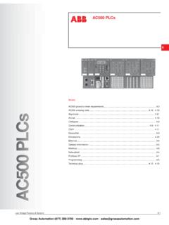
5 And is pin- andregister-compatiblewith the TexasInstrumentsSRC4382and V IOMULTI-CHPCMADCPCMPORTSS/PDIFPORTSDIX41 92 YesNoNo24 differentialLine IN and 1differentialLine OutPCM9211 NoYesYesUp to 3 IN and up to 3 OutUp to 12 single-endedINand up to 2 single-endedOutDIX9211 NoYesNoUp to 3 IN and up to 3 OutUp to 12 single-endedINand up to 2 single-endedOut363534333231302928272625 SYNCBLSAESOUTVDD33TX+TX-DGND2 GPO4 GPO3 GPO2 GPO1 MCLKBCKBLRCKBSDINBSDOUTBBGNDDGND3 VIONCSDOUTASDINALRCKABCKARXCKINCNCDGND1 VDD18 CPMCS/A0 CCLK/SCLCDIN/A1 CDOUT/SDAINTRST123456789101112RX1+RX1-RX 2+RX2-RX3+RX3-RX4+RX4-VCCAGNDLOCKRXCKO48 47 46 45 44 43 42 41 40 39 3813 14 15 16 17 18 19 20 21 22 2337244 DIX4192 SBFS031F FEBRUARY2006 :DIX4192 SubmitDocumentationFeedbackCopyright 2006 2016,TexasInstrumentsIncorporated(1)I = Input,O = Output,PWR= Power,GND= Ground7 Pin Configurationand FunctionsPFBP ackage48-PinTQFPTop ViewPin FunctionsPINTYPE(1) bufferedAES3-encodeddataAGND10 GNDDIR comparatorand PLL power-supplygroundBCKA37I/OAudioserialPo rt A bit clockBCKB48I/OAudioserialPort B bit clockBGND44 GNDS ubstrateground,connectto AGND(pin 10)BLS35I/ODIT blockstartclockCCLKor SCL20 ISerialdataclockfor SPI modeor I2C modeCDINor A121 ISPI port serialdatainputor programmableslaveaddressfor I2C modeCDOUTor SDA22I/OSPI port serialdataoutput(tri-stateoutput)or serialdataI/O for I2C modeCPM18 IControlport mode,0 = SPI mode,1 = I2C modeCS or A019 IChipselect(activelow)
6 For SPI modeor programmableslaveaddressfor I2C modeDGND116 GNDD igitalcoregroundDGND230 GNDDIR line receiverbias and DIT line driverdigitalgroundDGND343 GNDL ogicI/O FEBRUARY2006 REVISEDSEPTEMBER2016 ProductFolderLinks:DIX4192 SubmitDocumentationFeedbackCopyright 2006 2016,TexasInstrumentsIncorporatedPin Functions(continued)PINTYPE(1) (open-drain,activelow)LOCK11 ODIR PLL lock flag (activelow)LRCKA38I/OAudioserialPort A Left/RightclockLRCKB47I/OAudioserialPort B left/rightclockMCLK25 IMasterclockNC14, 15, 41 No internalsignalconnection,internallybonde dto ESDpadRST24 IReset(activelow)RX1+1 ILine receiver1, noninvertinginputRX1 2 ILine receiver1, invertinginputRX2+3 ILine receiver2, noninvertinginputRX2 4 ILine receiver2, invertinginputRX3+5 ILine receiver3, noninvertinginputRX3 6 ILine receiver3, invertinginputRX4+7 ILine receiver4, noninvertinginputRX4 8 ILine receiver4, invertinginputRXCKI13 IDIR referenceclockRXCKO12 ODIR recoveredmasterclock(tri-stateoutput)
7 SDINA39 IAudioserialPort A datainputSDINB46 IAudioserialPort B datainputSDOUTA40 OAudioserialPort A dataoutputSDOUTB45 OAudioserialPort B dataoutputSYNC36 ODIT internalsyncclockTX+32 ODIT line drivernoninvertingoutputTX 31 ODIT line driverinvertingoutputVCC9 PWRDIR comparatorand PLL powersupply, , line receiverbias and DIT line driversupply, supply, to V(1)StressesbeyondthoselistedunderAbsolu teMaximumRatingsmay causepermanentdamageto the stressratingsonly,whichdo not implyfunctionaloperationof the deviceat theseor any otherconditionsbeyondthoseindicatedunder RecommendedOperatingProcedures. Exposureto absolute-maximum-ratedconditionsfor extendedperiodsmay (unlessotherwisenoted)(1)MINMAXUNITP owersupplyVDD18 :digitallogicRXCKI,CPM,CS, CCLK,CDIN,CDOUT,INT, RST,MCLK,BLS,SYNC,BCKA,BCKB,LRCKA,LRCKB, SDINA,SDINB (VIO+ )VLine receiverinputvoltage(per pin)RX1+,RX1 , RX2+,RX2 , RX3+,RX3 , RX4+,RX4 (VDD33+ )VPPI nputcurrent(all pins exceptpowerand ground) 10mAAmbientoperatingtemperature 4085 CStoragetemperature,Tstg 65150 C6 DIX4192 SBFS031F FEBRUARY2006 :DIX4192 SubmitDocumentationFeedbackCopyright 2006 2016,TexasInstrumentsIncorporated(1)JEDE C documentJEP155statesthat 500-VHBM allowssafe manufacturingwith a standardESDcontrolprocess.
8 (2)JEDEC documentJEP157statesthat 250-VCDM allowssafe manufacturingwith a (ESD)ElectrostaticdischargeHuman-bodymod el(HBM),per ANSI/ESDA/JEDECJS-001(1) 2500 VCharged-devicemodel(CDM),per JEDEC specificationJESD22-C101(2) (unlessotherwisenoted) (1)For moreinformationabouttraditionaland new thermalmetrics,see theSemiconductorand IC PackageThermalMetricsapplicationreport, (1)DIX4192 UNITPFB(TQFP)48 PINSR C/WR JC(top)Junction-to-case(top) C/WR C/W C/W specificationsare at TA= 25 C, VDD18= V, VDD33= V, VIO = V, and VCC= V, CHARACTERISTICS(ALLI/O PINSEXCEPTLINERECEIVERSANDLINEDRIVER) VIOVIIHHigh-levelinputcurrentIO= 4 mA, MUTE,SDINA,and AIO= 4 mA, all 4 VIOVCINI nputcapacitance3pFLINERECEIVERINPUTS(RX1 +,RX1 , RX2+,RX2 , RX3+,RX3 , RX4+,RX4 )VTHD ifferentialinputsensitivityVoltageacross a givendifferentialinputpair150200mVVHYI nputhysteresis150mVLINEDRIVEROUTPUTS(TX+ ,TX )VTXOD ifferentialoutputvoltageRL= 110 AcrossTX+ and TX (MCLK) (MCLK)duty cycle45%55%DIGITALAUDIOINTERFACERECEIVER (DIR)PLL lock rangeTA= 25 C20216kHzfRXCKIR eferenceclockinput(RXCKI) (RXCKI)duty cycle45%55%fRXCKOR ecoveredclockoutput(RXCKO) FEBRUARY2006 REVISEDSEPTEMBER2016 ProductFolderLinks.
9 DIX4192 SubmitDocumentationFeedbackCopyright 2006 2016,TexasInstrumentsIncorporatedElectri calCharacteristics(continued)All specificationsare at TA= 25 C, VDD18= V, VDD33= V, VIO = V, and VCC= V, (1)The typicalVIO supplycurrentis measuredusingthe DIX4192 EVMevaluationmodulewith loadingfromthe supplycurrentis dependentuponthe loadingon the (RXCKO)duty cycle45%55%Recoveredclockoutput(RXCKO)in trinsicjitterMeasuredcycle-to-cycle250ps RMSDIGITALAUDIOINTERFACETRANSMITTER(DIT) IntrinsicoutputjitterMeasuredcycle-to-cy cle200ps RMSPOWERSUPPLIESS upplycurrent:initialstartupAll blockspowereddownby defaultIDD18 SVDD18= V10 AIDD33 SVDD33= V10 AIIOSVIO = V300 AICCSVCC= V10 ASupplycurrent:quiescentAll blockspoweredup with no clocksappliedIDD18 QVDD18= = :dynamicAll blockspoweredup, fS= 48 kHzIDD18 DVDD18= (1)VIO = V46mAICCDVCC= :high samplingrateAll blockspoweredup, fS= 192 kHzIDD18 HVDD18= V15mAIIOH(1)VIO = V47mAICCHVCC= :initialstartupAll blockspowereddownby default1mWTotalpowerdissipation:quiescen tAll blockspoweredup with no clocksapplied28mWTotalpowerdissipation:d ynamicAll blockspoweredup, fS= 48 kHz233mWTotalpowerdissipation.
10 High samplingrateAll blockspoweredup, fS= 192 (PORTA ANDPORTB)fLRCKLRCK clockfrequency0216kHztLRCKDLRCK clockduty cycle50% pulsewidth10nstBCKLBCKlow pulsewidth10nstAISA udiodataInput(SDIN)set-uptime10nstAISHA udiodatainput(SDIN)hold time10nstADDA udiodataoutput(SDOUT)delay10nsHOSTINTERF ACE:SPI MODEfCCLKS erialclock(CCLK)frequency040 MHztCSCRCS fallingto CCLK rising8nstCFCSCCLK fallingto CS rising7nstCDSCDIN dataset-uptime7ns8 DIX4192 SBFS031F FEBRUARY2006 :DIX4192 SubmitDocumentationFeedbackCopyright 2006 2016,TexasInstrumentsIncorporatedTimingR equirements(continued)MINNOMMAXUNIT(1)Al l valuesreferredto the VIHminimumand VILmaximumlevelslistedin the DigitalI/O Characteristicssectionof this table.(2)A devicemustinternallyprovidea hold time of at least300 ns for the SDAsignal(referredto the VIHminimuminputlevel)to bridgetheundefinedregionof the fallingedgeof SCL.