Transcription of INTRODUCTION TO CMOS CIRCUITS CONTENTS
1 UNIT II INTRODUCTION TO cmos CIRCUITS CONTENTS 1. INTRODUCTION 2. cmos FABRICATION n-well cmos process p-well cmos process Twin -Tub Process 3. LOGIC GATES cmos Inverter NAND Gate NOR Gate 4. STICK DIAGRAM AND LAYOUT REPRESENTATION Components in cmos technology cmos Joining Rules Inverter stick diagrams NAND gate stick diagrams NOR gate stick diagram 5. LAYOUT DESIGN RULES 6. SCALING OF cmos CIRCUITS 7. OTHER cmos LOGIC Pseudo nMOS Logic Clocked cmos Logic( C2 MOS Logic) Dynamic cmos Logic cmos Domino Logic n-p cmos LOGIC 1. INTRODUCTION One of the most popular MOSFET technologies available today is the Complementary MOS or cmos technology. cmos technology is the dominant semiconductor technology for microprocessors, memories and application specific integrated CIRCUITS (ASICs). The main advantage of cmos over NMOS and BIPOLAR technology is the much smaller power dissipation.
2 Unlike NMOS or BIPOLAR CIRCUITS , a cmos circuit has almost no static power dissipation. Power is only dissipated in case the circuit actually switches. This allows to integrate many more cmos gates on an IC than in NMOS or bipolar technology, resulting in much better performance. In cmos technology, both N-type and P-type transistors are used to realize logic functions. The same signal which turns on a transistor of one type is used to turn off a transistor of the other type. This allows the design of logic devices using only simple switches, without the need for a pull-up resistor. In cmos logic gates a collection of n-type MOSFETs is arranged in a pull-down network between the output and the lower voltage power supply rail (Vss or quite often ground). Instead of the load resistor of NMOS logic gates, cmos logic gates have a collection of p-type MOSFETs in a pull-up network between the output and the higher-voltage rail (often named Vdd).
3 Thus, if both a p-type and n-type transistor have their gates connected to the same input, the p-type MOSFET will be on when the n-type MOSFET is off, and vice-versa. 2. cmos FABRICATION There are a number of approaches to cmos fabrication, including the p-well, the n-well, the twin tub and the silicon - on insulator processors. n-well cmos process Step 1: Si Substrate The n-well cmos process starts with a moderately doped (with impurity concentration around 2 1021 impurities/m3) p-type silicon substrate. p substrate Step 2: Oxidation This step deposits a thin layer of SiO2 over the complete wafer by exposing it to high-purity oxygen and hydrogen at approx. 1000oC p substrateSiO2 Step 3: Photoresist Coating Photoresist is a light sensitive polymer evenly applied to a thickness of 1 m by spinning the wafer. This photoresist cross link when exposed to light, making the affected regions insoluble p substrateSiO2 Photoresist Step 4: Masking The first lithographic mask defining the n-well region is brought in close proximity to the wafer.
4 The mask is opaque in the regions we want to process and transparent in the other regions The combination of mask and wafer is now exposed to Ultraviolet rays. Where the mass is transparent, the photoresist becomes insoluble. Uv rays Step 5: Removal of Photoresist The soluble photoresist are removed by treating the wafer with acidic or basic solution. Then the wafer is soft baked at low temperature to harden the the remaining photoresist p substrateSiO2 Photoresistn-type mask p substrateSiO2 Photoresist Step 6: Acid Etching SiO2 is selectively removed from areas of wafer that are not covered by photoresist by using hydrofluoric acid. Photoresistp substrateSiO2 Step 7: Removal of Photoresist Strip off the remaining photoresist p substrateSiO2 Step 8: Formation of n-well n-well is formed by diffusion or ion implantation.
5 DIFFUSION In diffusion, the wafers are placed in a quartz tube embedded in a heated furnace. A gas containing the dopant is introduced in the tube. The high temperatures of the furnace (900 to 1000oC) cause the dopants to diffuse into the exposed surface both vertically and horizontally ION IMPLANTATION Dopants are introduced as ions into the material. The ion implantation system directs and sweeps a beam of purified ions over the semiconductor surface. The acceleration of ions determines how deep they will penetrate the material, while the beam current and the exposure time determine the dosage. n wellSiO2 Steps 2 to 8 constitutes the photolithographic process. Step 9: Removal of SiO2 Strip off the remaining oxide using HF and we have bare wafer with n-well p substraten well Step 10: Polysilicon deposition Deposit very thin layer of gate oxide and then using chemical vapor deposition process a layer of polysilicon is deposited.
6 In this process silane gas flows over the heated wafer coated with SiO2 at a temperature of approx. resulting reaction produces a noncrystaline or amorphous material called polysilicon. Use same lithography process to pattern polysilicon Step 11: N- diffusion Carry on photolithographic process to diffuse n- type material. N-diffusion forms nMOS source, drain, and n-well contact. Thin gate oxidePolysiliconp substraten wellp substrateThin gate oxidePolysiliconn wellOxidation Step 12: P- diffusion p substraten well Uv rays n+ Diffusionp substraten wellMasking p substraten welln wellp substraten+n+Etching n+Diffusion or Ion implantation n wellp substraten+n+n+Removal of SiO2 p substrate Step 11 repeated with p diffusion mask produces pMOS source ,drain and substrate contact. n+n+p+p+p+n+n well Step 13: Contact cuts Now we need to wire the devices.
7 Cover chip with thick field oxide. Etch oxide where contact cuts are needed Step 14: Metallization Aluminum interconnect layers are deployed using a process known as Sputtering. Aluminum is evaporated in vacuum with heat for evaporation delivered by electron-beam or ion-beam bombarding. Other metal interconnects such as copper require different deposition techniques. p-well cmos process The fabrication of p-well cmos process is similar to n-well process except that p-wells acts as substrate for the n-devices within the parent n-substrate Advantages of n-well process n-well cmos are superior to p-well because of lower substrate bias effects on transistor threshold voltage lower parasitic capacitances associated with source and drain region Latch-up problems can be considerably reduced by using a low resistivity epitaxial p-type substrate p substrateThick field oxiden+n+p+p+p+n+n wellMetalThick field oxidep substraten welln+n+p+p+p+n+ However n-well process degrades the performance of poorly performing p-type transistor Twin -Tub Process A combination of p-well and n-well process is the Twin-Tub process.
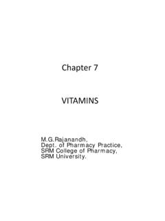
8 Here we start with a substrate of high resistivity n-type material and then create both n-well and p-well regions. It is possible to preserve the performance of n-type transistors without compromising the p-type transistors In general, the Twin-tub process allows separate optimization of the n and p transistors 3. LOGIC GATES cmos INVERTER The circuit below is the simplest cmos logic gate. cmos inverter When a low voltage (0 V) is applied at the input, the top transitor (P-type) is conducting (switch closed) while the bottom transitor behaves like an open circuit . Therefore, the supply voltage (5 V) appears at the output. Conversely, when a high voltage (5 V) is applied at the input, the bottom transitor (N-type) is conducting (switch closed) while the top transitor behaves like an open circuit .
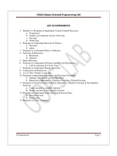
9 Hence, the ouput voltage is low (0 V). The function of this gate can be summarized by the following table: Input Output High(1)Low(0)Low(0)High(1) The output is the opposite of the input this gate inverts the input. Notice that always one of the transistor will be an open circuit and no current flows from the supply voltage to ground. NAND Gate NAND circuit and Standard Symbol The circuit has two inputs and one output. Whenever at least one of the inputs is low, the corresponding P-type transistor will be conducting while the N-type transistor will be closed. Consequently, the ouput voltage will be high. Conversely, if both inputs are high, then both P-type transistors at the top will be open CIRCUITS and both N-type transistors will be conducting. Hence, the output voltage is low. The function of this gate can be summarized by the following table: V1 V2 OutputLowLowHigh LowHighHigh HighLowHigh HighHighLow If logical 1 s are associated with high voltages then the function of this gate is called NAND for negated AND.
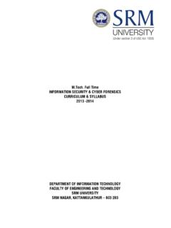
10 Again, there is never a conducting path from the supply voltage to ground. NOR Gate NOR circuit and Standard Symbol The circuit has two inputs and one output. Whenever at least one of the inputs is high, the corresponding N-type transistor will be closed while the P-type transistor will be open. Consequently, the ouput voltage will be low. Conversely, if both inputs are low, then both P-type transistors at the top will be closed CIRCUITS and the N-type transistors will be open. Hence, the output voltage is high. The function of this gate can be summarized by the following table: V1 V2 OutputLowLowHigh LowHighLow HighLowLow HighHighLow If logical 1's are associated with high voltages then the function of this gate is called NOR for negated OR. Again, there is never a conducting path from the supply voltage to ground. 4. STICK DIAGRAM AND LAYOUT REPRESENTATION Stick diagrams and layout representation are used to convey layer information through the use of a color code.