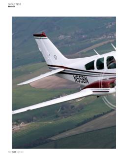
Transcription of IO-520 Overhaul Manual - CSOBeech.com
1 Publication X30039 2011 CONTINENTAL MOTORS, 2011IO-520 CONTINENTAL AIRCRAFT ENGINE OVERHAULMANUALTECHNICAL CONTENT ACCEPTED BY THE FAA AIO-520 Series Engine Overhaul Manual31 August 2011 Supersedure NoticeThis Manual revision replaces the front cover and list of effective pages for Publication Part No. X30039, datedSeptember 1977. Previous editions are obsolete upon release of this Changes for this Manual0 .. September 19771 .. 31 August 2011 List of Effective PagesDocument Title: IO-520 Series Engine Overhaul ManualPublication Number: X30039 Initial Publication Date: September 1A .. 1i thru v .. 01-1 thru 02-1 thru 03-1 thru 04-1 thru 05-1 thru 06-1 thru 07-1 thru 08-1 thru 09-1 thru 010-1 thru 0 Published and printed in the by Continental Motors, exclusively from the publisher: Box 90, Mobile, AL 36601 Copyright 2011 Continental Motors, Inc.
2 All rights reserved. This material may not be reprinted, republished, broadcast, or otherwisealtered without the publisher's written permission. This Manual is provided without express, statutory, or implied warranties. The publisher willnot be held liable for any damages caused by or alleged to be caused by use, misuse, abuse, or misinterpretation of the contents. Content issubject to change without notice. Other products and companies mentioned herein may be trademarks of the respective October 1978 October 1978 v Intentionally Left Blank MAY 1980 1-1 SECTION IINTRODUCTION1-1. SCOPE. This publication comprisesOverhaul Instructions for the IO-520 Series RELATED PUBLICATIONS.
3 Detail partnumbers and service assemblies for these enginemodels are contained in Parts Catalog instructions are contained in Operator'sHandbook Service instructions for Slick Magneto ModelNo. 662 may be obtained from Slick Electro Inc.,Rockford, Illinois Service instructions for Bendix MagnetoModel S6RN-201, S6RN-205, S6RN-1201 andS6RN-1205 may be obtained from BendixCorporation, Electrical Components Division,Sidney, New York Service instructions for Delco-Remy Starters,Generators or Alternators may be obtained fromDelco-Remy Division, General Motors Corporation,Anderson, Indiana SERVICE BULLETINS.
4 Importantchanges and product improvements are covered byfactory service bulletins available for study at allApproved Distributors. These Bulletins are alsoavailable to owners, operators or maintenancepersonnel on an annual subscription SERVICE REPORTS AND is the policy of Teledyne Continental Motors tohandle all reports of service difficulty and requestsfor information through Approved for further copies of this or any otherTeledyne Continental Aircraft Engine ServicePublication should be made through these is an Approved Distributor at every CYLINDER ARRANGEMENT.
5 Cylindersare numbered starting from the rear, with oddnumbers on the right and even numbers on the DEFINITIONS AND ABBREVIATIONSTerm . Explanation After Bottom CenterApprox. After Top CenterBar. Before Bottom Brake horsepowerB. Before Top Federal Aviation Civil Air Cubic feet per Center of GravityDia. Diameter Degrees of Angle F. Degrees FarenheitFig.
6 Figure (Illustration)Front Propeller Endft. foot or .M. Gallons per minuteH2O WaterHg. Inside Diameterin. (") InchesHex. Hexagonhr. HourLeft Side Side on which Nos. 2, 4 and6 cylinders are locatedLbs. PoundsLockwire Soft steel wire used to safetyconnections, Manifold or manometerMax.
7 MaximumMin. Minimum30' thirty minutes of angle(60' equal one degree) National pipe thread(tapered)1-2 Term . Explanation Coarse (thread) Fine (thread) per square inchRearAccessory end of engineRight SideSide on which Nos. 1, 3 and5 cylinders are per dead x lever arm (125 applied one ft. from boltcenter or 62-1/2 lbs. applied2 ft. from center)TABLE I. PURCHASED ACCESSORIESACCESSORYQTYM agneto ..2 Starter ..1 Alternator ..1 Generator ..1 Oil Cooler ..1 Fuel II. IGNITION SYSTEM DETAILSFEATUREVALUELeft Magneto Lower No. 1-3-5 And Upper No.
8 2-4-6 plugsRight Magneto Upper No. 1-3-5 And Lower No. 2-4-6 plugsFiring order (cylinder numbers) ..1-6-3-2-5-4 Permissible RPM spread whenSwitched from Both to either Left or Right DEFINITION OF TERMS. Front, rear, leftand right, as used in this Manual , refer to the engineas viewed by the mechanic in a normal position,facing the accessory AND DIMENSIONSDIMENSIONVALUEP iston stokes per cylinder ..4 Number of cylinders ..6 Cylinder bore (inches) .. stroke (inches) .. IV. TEMPERATURE LIMITSINDICATED temperature at takeoff75 F--Oil temperature in flight--240 head temperature(bayonet thermocouple)*--460 temperature(at coil hold-down screw)--170 F.
9 * Installed in tapped hole in bottom of cylinder V. PRESSURE pressure (idling)10 psi--Oil pressure (in flight)30 psi60 psiOil pressure (with cold oil)--100 psiTABLE VI. VISCOSITY OIL GRADESOIL OPERATINGOILTEMPERATUREGRADE Below 40 F. 30 OR 10W-30 Above 40 Ambient air temperature is the controlling factor on allengines having oil temperature control valves OIL SUPPLY AND The capacity of the oil sump is 12 oil filler cap is attached over the oil filler neckon top of the left crankcase. The oil sump isequipped with an oil level gauge notched andstamped with numerals representing OIL When operated on a rigid test stand at cruisepower settings and operating within specified limitsoil consumption shall not exceed 1 quart per hourand one 1-1.
10 THREE-QUARTER RIGHT FRONT VIEW OF THE IO-520 -A,E,F & K. (SANDCAST CASE)FIGURE 1-2. THREE-QUARTER REAR VIEW OF THE IO-520 -A & F. (SANDCAST CASE)1-4 FIGURE 1-3. THREE-QUARTER RIGHT FRONT VIEW OF THE IO-520 -B. (PERMOLD CRANKCASE)FIGURE 1-4. THREE-QUARTER LEFT REAR VIEW OF THE IO-520 -B. (PERMOLD CASE)1-5 FIGURE 1-5. THREE-QUARTER RIGHT FRONT VIEW OF THE IO-520 -C. (PERMOLD CASE)FIGURE 1-6. THREE-QUARTER LEFT REAR VIEW OF THE IO-520 -C. (PERMOLD CASE)1-6 FIGURE 1-7. THREE-QUARTER RIGHT FRONT VIEW OF THE IO-520 -D. (SANDCAST CRANKCASE)FIGURE 1-8. THREE-QUARTER LEFT REAR VIEW OF THE IO-520 -D. (SANDCAST CRANKCASE)1-7 FIGURE 1-9. THREE-QUARTER RIGHT FRONT VIEW OF THE IO-520 -J.