Transcription of IQSmoke (QS5110-840) Wireless Smoke Heat Alarm ...
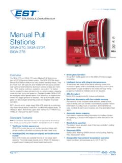
1 ATTENTION: This manual should be read prior to use and retained for further INFORMATIONThe Wireless Smoke Heat Alarm is a 3xAAA battery powered Wireless detector intended for use with a compatible Wireless Alarm system. The detector has a built-in Wireless transmitter, which communicates with the control panel. When Smoke is detected, the Alarm sounds a loud local Alarm and the built-in transmitter sends a signal to the control panel. The Wireless Smoke Heat Alarm contains an integrated fi xed 41 F temperature freeze sensor that will send a warning signal based on temperature detected. This detector is designed to provide protection with 70-foot spacing detector can send Alarm , tamper and battery condition messages to the system s receiver. Refer to the Wireless system s instruction for the maximum number of transmitters that can be OF BOX.
2 Wireless Smoke Heat Alarm with base Installation guide (APD0595) Pack of screws and anchors Labels or decals as appropriate 3 AAA PC2400 Duracell Procell batteries ( 1100mAh) or 3 AAAE nergizer E92 batteries ( 1100mAh) IQSmoke (QS5110-840) Wireless Smoke Heat AlarmInstallation Guide2 INST APD0595 A140618 Wireless Smoke Heat Alarm Install GuideStatusLEDsSounder(do not pulse the sounderand LED concurrently)NormalGreen fl ash every 12 secondsOffHeat AlarmRed fl ash every 1 secondANSI temporal 3 Heat TestRed fl ash every 1 secondANSI temporal 3 Smoke AlarmRed fl ash every 1 secondANSI temporal 3(press button to hushfor 5-10 minutes) Smoke TestRed fl ash every 1 secondANSI temporal 3 (press button to hushfor 5-10 minutes)Test AlarmRed fl ash every 1 secondANSI temporal 3 Freeze Warning3 yellow fl ashesevery 4 secondsOffDetector TroubleYellow fl ash every 4 secondsOne chirp every 48 secondsLow BatteryYellow fl ash every 12 secondsOne chirp every 48 seconds (press button to hush for 12 hours)Detector DirtyYellow fl ash every 8 secondsOne chirp every 48 secondsPower-upRed, yellow, greenfl ash sequenceOne chirp at the endof power-up sequenceTamperRed, yellow, green fl ashsequence every 12 secondsOffThe Wireless Smoke Heat Alarm contains a sounder which generates the ANSI temporal 3 pattern in an Alarm condition.
3 In Alarm , a message is also sent to the control panel and the detector s ID is displayed at the console. During an Alarm condition, pressing the detector s hush button will silence the sounder (see table below). The mounting base installation is simplifi ed by the incorporation of features compatible for both drywall fasteners (not supplied) and other LED (red, yellow, green) and a sounder on the detector provide local visual and audible indication of the detector s status as listed in Table 1. During initial power-up the LED blinks alternately red, yellow then green. It takes about 8 seconds for the detector to power-up has completed and the detector is functioning normally, the green LED blinks once every 12 Trouble: When the detector has a general fault, the yellow LED blinks once every four seconds and there is a chirp every 48 seconds.
4 After 12 hours the panel will display a loss of supervision 1. Detector status and indicationQolsys1900 The Alameda, Suite 420 San Jose, CA Support: 1-855-476-579722 Guide d'installation du d tecteur de chaleur et de fum e sans fi l INST APD0595 A140618 Cette r impression n exprime pas la position compl te et offi cielle de la National Fire Protection Association sur le sujet cit qui est repr sent uniquement par la norme dans son int gralit .)(Code national d alarme incendie et NFPA 72 sont des marques d pos es de la National Fire Protection Association, Inc., Quincy, MA 02269.) Dans les maisons d'habitation niveau unique et plusieurs niveaux ainsi que dans les immeubles d'habitation quip s de syst mes de d tecteurs de fum e similaires, il est possible que les signaux envoy s par des capteurs sans fi l soient bloqu s ou r fl chis par le m tal avant d'atteindre le panneau de commande du d tecteur et ce, m me si le parcours du signal a t r cemment v rifi au cours d'un test hebdomadaire.
5 Un blocage peut se produire si un objet m tallique a t d plac dans le parcours du signal du APD0595 A140618 Wireless Smoke Heat Alarm Install GuideDetector Dirty Feature: When the detector has been contaminated, the yellow LED blinks once every 8 seconds and there is a chirp every 48 seconds. Refer to MAINTENANCE section for cleaning your Alarm . After 12 hours the panel will display a loss of supervision Battery Detection: The Wireless Smoke Heat Alarm is powered by 3 AAA Duracell Procell or 3 AAA Energizer E92 batteries (included). The detector regularly checks for a low battery. If a low battery is detected, the transmitter sends a low battery message to the control panel, which displays the detector s ID at low battery. In addition, the yellow LED of the detector will blink every 12 seconds.
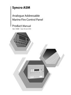
6 The detector s sounder will chirp every 48 seconds (yellow LED continues to blink) until the batteries are replaced. Pressing the hush button will silence the chirps for 12 hours, if no other trouble conditions exist. The batteries should be replaced WHEN the chirps begin. Be sure to replace the batteries with fresh INSTALLATION AND REPLACEMENTTo replace the batteries:1. Remove the detector from its mounting base by twisting thedetector counterclockwise. Remove and dispose of the batteriesaccording to your local To ensure proper power-down sequence, wait a minimum of 20seconds before installing new Install 3 new AAA batteries (available from your local Duracell orEnergizer dealer) in the battery compartment. Follow the polaritydiagram inside the compartment.
7 If the batteries are incorrectlyinserted please remove gently with a non-conductive tool andcorrectly $77(5< &203$570(17 HUSH/TEST BUTTONFig 1. Wireless Smoke Heat Alarm4 INST APD0595 A140618 Wireless Smoke Heat Alarm Install Guide4. Reinstall the detector onto the mounting base by turning thedetector clockwise until the mating marks After the power-up sequence the green LED should blink aboutonce every 12 seconds to indicate normal operation. If the batteriesare not installed correctly, the detector will not operate and thebatteries may be damaged. If the detector does not power-up, checkfor correct batteries installation and for a fully charged Test the detector (as described later).CONSTANT EXPOSURES TO HIGH OR LOW TEMPERATURES OR HIGH HUMIDITY MAY REDUCE BATTERY to the appropiate compatible control panel programming guide for the proper procedure required to enroll the Wireless Smoke /heat into the LOCATIONS FOR Smoke HEAT ALARMA ccording to National Fire Protection Association (NFPA) the major threat from fi re in a dwelling unit occurs at night when everyone is asleep.))
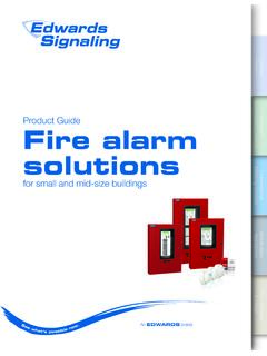
8 The principal threat to persons in sleeping areas comes from fi res in the remainder of the unit; therefore, a Smoke detector(s) is best located between the bedroom areas and the rest of the unit. In units with only one bedroom area on one fl oor, the Smoke detector(s) should be located as shown in Figure 2. In dwelling units with more than one bedroom area or with bedrooms on more than one fl oor, more than one Smoke detector is required, as shown in Figure addition to Smoke detectors outside of the sleeping areas, the device should be installed on each additional story of the dwelling unit, including the basement. These installations are shown in Figure 4. The living area Smoke detector should be installed in the livingroom or near the stairway to the upper level, or in both locations.
9 Thebasement Smoke detector should be installed in close proximity to thestairway leading to the fl oor above. Where installed on an open-joistedceiling, the detector should be placed on the bottom of the joists. Thedetector should be positioned relative to the stairway so as to interceptsmoke coming from a fi re in the basement before the Smoke enters detectors are optional where a door is not provided between living room and recreation room (Figure 5). The Smoke from a fi re generally rises to the ceiling, spreads out across the ceiling surface, and begins to bank down from the ceiling. The corner where the ceiling and wall meet is an air space into which the Smoke could have diffi culty 21 Guide d'installation du d tecteur de chaleur et de fum e sans fi l INST APD0595 A140618 Des changements ou modifi cations non autoris s pourraient entra ner l annulation de l autorisation d exploiter l appareil est conforme la partie 15 de la r glementation de la FCC et aux normes RSS sur les appareils exempts de licence d'Industrie Canada.
10 Son fonctionnement est soumis aux deux conditions suivantes : (1) Ce dispositif ne doit pas causer d interf rences nuisibles, et (2) cet appareil doit accepter toute interf rence re ue, y compris les interf rences pouvant causer un fonctionnement inopin de l quipement a t test et d clar conforme aux limites applicables aux p riph riques num riques de classe B, selon la partie 15 de la r glementation de la FCC. Ces limites ont t con ues pour fournir une protection raisonnable contre les interf rences nuisibles en milieu r sidentiel. Cet quipement produit, utilise et peut mettre de l nergie de fr quence radio. Si l quipement n est pas install et utilis conform ment aux instructions fournies, il peut provoquer des interf rences n fastes aux communications radio. Cependant, la possibilit qu'une interf rence se produise dans une installation particuli re n est pas totalement exclue.