Transcription of Isolation Fault Troubleshooting - Application Note
1 Isolation Fault Troubleshooting - Application NoteVersion HistoryVersion - August 2022 - 1000V testing supported on S-Series optimizersVersion - October 2021 - Updated tester-to-module connection schemeVersion - October 2021 - 'Checking the DC Voltage' procedure updated, error codes updatedContentsIntroduction1 Identifying an Isolation Fault1 Troubleshooting an Isolation Fault (Using the Inverter LCD Display or SetApp)2 Using an Insulation Tester7 IntroductionIn photovoltaic systems with a transformer-less inverter, the DC is isolated from ground. Modules with defective module Isolation , unshielded wires, defective power optimizers, or an inverter internal Fault can cause DC current leakage to ground (PE - protective earth). Such a Fault is also called an Isolation Fault . This document describes how to identify and locate an Isolation Fault in a SolarEdge !
2 This guide is intended to aid in Troubleshooting a SolarEdge installation which has a ground Fault . Persons using this guide should be completely familiar with SolarEdge systems, their concept of operation, safety features, and all applicable safety procedures and requirements. Do not attempt any Troubleshooting without adequate safety equipment and a thorough understanding of all procedures. WARNING! Troubleshooting of PV systems may involve exposure to hazardous voltage levels and should be conducted by qualified personnel only. Presence of ground faults in PV systems may result in hazardous voltages or currents on normally grounded conductors or exposed metal elements. Extreme caution must be used when Troubleshooting PV systems with ground an Isolation FaultEvery time the SolarEdge inverter enters operational mode and starts producing power, the resistance between the ground and the DC current-carrying conductors is checked.
3 The inverter displays an Isolation error when it detects a total combined Isolation resistance of less than 600k in single phase inverters, or 1M in three phase inverters. You can identify an Isolation Fault usingSetAPPThe inverter LCD displayAn Isolation Fault may disappear and recur after a short period (especially if it is caused by morning moisture), therefore it is recommended to troubleshoot the Fault as soon as it occurs, before it may temporarily disappear. Before Troubleshooting on site, you may check the Isolation value in the SolarEdge monitoring platform. If the value is borderline (within 10%) or below the limit (600k for single phase inverters / 1M for three phase inverters), troubleshoot the Fault on site. If the value is at least 10% higher than the limit, it is better to wait until an Isolation Fault error recurs.
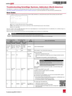
4 To check the Isolation value in the monitoring platform: 1. In the Layout window right-click on the inverter and select Choose operations Reset. 2. Right-click on the inverter and select Info to display information about the inverter. 3. In the General parameter list, check the Last Isolation 1: System data tab in the Details windowIdentifying an Isolation Fault Using SetAppIf an Isolation error occurs, error 18x86 (single phase inverters) or 8x58 (three phase inverters) is displayed in the SetApp Status screen (see following figures).To access the SetApp status screen and view error details: 1. From the Commissioning menu select Status. The inverter Status is displayed (see following figures) 2. Tap the error line for and Language Pairing Communication Device Manager Maintenance Information Site Configuration Status StatusError: Isolation 121 Inverter SN 07318000 CPower 2 kWVoltage230 VacFrequency50 Hz P_OK: 7 of 8 Optimizers ConnectedS_OKServer LimitCountryNetherlandsVoltage310 VdcTemp20 CFanN/AError: 18X: V-Line MaxSwitch OFF.
5 Production disabledCommissioningIdentifying an Isolation Fault Using the Inverter LCD DisplayIf an Isolation error occurs, the LCD displays error 2x19 (single phase inverters) or 8x58(three phase inverters):E r r o r x x x x I s o l a t i o n f a u l t S e e d i a g n o s t i c s Troubleshooting an Isolation Fault (Using the Inverter LCD Display or SetApp)The next sections describe how to identify the source of an Isolation Fault if Error 2x19 or 8x58 are displayed. You can troubleshoot the Isolation Fault using the following methods:IsolationFaultTroubleshooting-Ap plicationNote2 TroubleshootinganIsolationFault(Usingthe InverterLCDD isplayorSetApp)The Inverter Diagnostics Screen in the LCD Display or the Status Screen in SetApp. NOTEIf using the LCD Display, this method is available from DSP1 firmware version in three-phase inverters, and in single phase inverters.
6 The version can be checked from the ID status screen of the LCD. If required, upgrade the inverter software as described in insulation tester (Megger).Checking the DC VoltageDuring the Troubleshooting process, strings and/or power optimizers will be disconnected. 1. Turn the inverter ON/OFF switch at the bottom of the inverter to OFF. If a Safety Switch or a DC Isolation switch is installed, it should remain ON. 2. Wait until the DC voltage is safe. 3. Remove the required string, power optimizer or module. 4. Turn the inverter ON, and check that Vdc, shown in the inverter screen below, is approximately the nominal DC voltage according to the following table: Inverter typeEurope & APACN orth AmericaUnitSingle phase350350 VdcThree phase750 For 208V 400 VdcFor Medium Voltage 850 For 277/ 480V 850 Vdc V a c [ V ] V d c [ V ] P a c [ W ] 2 4 0.
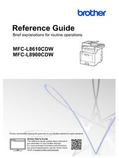
7 7 3 7 1 . 9 2 3 4 9 . 3 P _ O K : X X X / Y Y Y < S _ O K > O N StatusError: Isolation 18x86 Inverter SN 07318000 CPower 2 kWVoltage230 VacFrequency50 Hz P_OK: 7 of 8 Optimizers ConnectedS_OKServer LimitCountryNetherlandsVoltage310 VdcTemp20 CFanN/AError: 18X: V-Line MaxSwitch OFF. Production disabledCommissioningLocating the Leaking String 1. If multiple strings are connected to the inverter, find the faulty string by connecting one string at a time to the inverter and checking if the error is still displayed (follow the procedure Identifying an Isolation Fault Using SetApp on page 2). 2. Verify that only the faulty string is connected to the inverter. If there is more than one faulty string, check each string (UsingtheInverterLCDD isplayorSetApp) 3 Locating the Leakage within a String Using the Inverter LCD Display 1.
8 Enter the Isolation status screen by pressing and holding down the LCD light button until the following message is displayed:K e e p h o l d i n g b u t t o n f o r p a i r i n g , r e l e a s e t o e n t e r m e n u .. R e m a i n i n g : 3 s e c 2. Release within 5 seconds to enter setup mode. 3. Short-press (one second) to scroll down to the Maintenance menu and long-press to enter the menu. The following screen is displayed:D a t e a n d T i m e R e s e t C o u n t e r s F a c t o r y R e s e t F W U p g r a d e D i a g n o s t i c s G r i d P r o t e c t i o n B o a r d R e p l a c e m e n t 4. Short-press to scroll down to the Diagnostics menu and long -press to select Diagnostics Isolation Status. The following status screen is displayed:R I s o 4 0 0 k O h m D C + D C - | - - - - - - - * - - - - - - - - - - | < 4 0.
9 3 % > R Iso: The value of the Isolation resistance (in kOhm)The asterisk (*) and the percentage value indicate the approximate location of the Fault within the string, relative to DC+:0% indicates the Fault is at DC+100% indicates the Fault is at DC- 5. Using the screen, identify the Fault source area: Multiply the number of power optimizers in the string by the percentage value. The result is the module near which the Fault occurred. For example, in a string with 15 modules and power optimizers and a percentage value of 55%: 15*55% = This means that the Fault is near module #8, counted from the DC+ side. 6. Check if there are damaged connectors or DC wires between the suspected power optimizer and its module and between the suspected power optimizer and its neighboring power optimizers. If there are, replace them and recheck the Isolation status by turning ON the inverter as described in Identifying an Isolation Fault Using SetApp on page 2.
10 If the Fault persists, proceed to the next step. 7. Remove the suspected Fault source by disconnecting the suspected power optimizer from the string (following the steps in Identifying an Isolation Fault Using SetApp on page 2). Use a DC extension cable with MC4 connectors (male at one end and female at the other end) to bypass the removed power optimizer. Recheck the Isolation after startup/pairing the Fault is eliminated, the Fault is in the removed module/power optimizer. Proceed to the next after startup/pairing the Fault re-appears, the leakage source is not in the removed module/power optimizer but near it. 8. Reconnect the module/power optimizer in the the modules/power optimizers before and after the suspected location by repeating steps 6 and 7, one module/power optimizer at a time. If the Fault re-appears, check the next modules/power optimizers one a location of the Fault is detected with an accuracy of 1 for single phase inverters and 2 for three phase inverters.