Transcription of K1010 Series - cosmo-ic.com
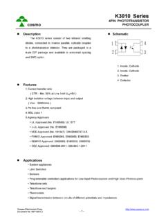
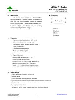
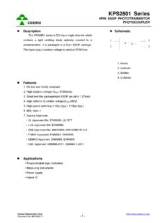
1 K1010 Series 4 PIN PHOTOTRANSISTOR. cosmo PHOTOCOUPLER. Description Schematic The K1010 Series consist of an infrared emitting diode, optically coupled to a phototransistor detector. They are packaged in a 4-pin DIP package and available in wide-lead spacing and SMD option. 1. Anode 2. Cathode 3. Emitter 4. Collector Features 1. Current transfer ratio ( CTR Min. 50% at IF=5mA VCE=5V ). 2. High isolation voltage between input and output ( Viso 5000 Vrms ). 3. Pb free and RoHS compliant 4. MSL class 1. 5. Agency Approvals UL Approved (No. E169586): UL1577. c-UL Approved (No. E169586). VDE Approved (No. 101347): DIN EN60747-5-5. FIMKO Approved: EN60065, EN60950, EN60335. SEMKO Approved: EN60065, EN60950, EN60335.
2 CQC Approved: GB8898-2011, Applications System appliances Measuring instruments Computer terminals Programmable controllers Medical instruments Physical and chemical equipment Signal transmission between circuits of different potentials and impedances Cosmo Electronics Corp. Document No. -1- K1010 Series 4 PIN PHOTOTRANSISTOR. cosmo PHOTOCOUPLER. Outside Dimension Unit : mm type. mount type. K10101X K10104X. 0~10 .. creepage distance type creepage distance for surface mount type. K10103X K10106X. 0~10 . + TOLERANCE Device Marking Notes: cosmo 1010 cosmo 817 1010. YWW 817. YWW Y: Year code / WW: Week code : CTR rank Cosmo Electronics Corp. Document No. -2- K1010 Series 4 PIN PHOTOTRANSISTOR. cosmo PHOTOCOUPLER.
3 Absolute Maximum Ratings (Ta=25 ). Parameter Symbol Rating Unit Forward current IF 50 mA. Peak forward current IFM 1 A. Input Reverse voltage VR 6 V. Power dissipation PD 70 mW. Collector-emitter voltage VCEO 80 V. Emitter-collector voltage VECO 6 V. Output Collector current IC 50 mA. Collector power dissipation PC 150 mW. Total power dissipation Ptot 200 mW. Isolation voltage 1 minute Viso 5000 Vrms Operating temperature Topr -55 to +115 . Storage temperature Tstg -55 to +125 . Soldering temperature 10 seconds Tsol 260 . Electro-optical Characteristics (Ta=25 ). Parameter Symbol Conditions Min. Typ. Max. Unit Forward voltage VF IF=20mA - V. Peak forward voltage VFM IFM= - - V. Input Reverse current IR VR=4V - - 10 A.
4 Terminal capacitance Ct V=0, f=1 KHz - 30 - pF. Output Collector dark current ICEO VCE=20V, IF=0 - - A. IF=5mA, VCE=5V 50 - 600. Current transfer ratio CTR %. IF=1mA, VCE=5V 15 - - Collector-emitter saturation VCE(sat) IF=20mA, IC=1mA - V. 10 11. Transfer Isolation resistance Riso DC500V 5x10 10 - . charac- teristics Floating capacitance Cf V=0, f=1 MHz - pF. Cut-off frequency fC VCC=5V, IC=2mA, RL=100 - 80 - KHz Response time (Rise) tr - 4 18 s VCE=2V, IC=2mA, RL=100 . Response time (Fall) tf - 3 18 s Cosmo Electronics Corp. Document No. -3- K1010 Series 4 PIN PHOTOTRANSISTOR. cosmo PHOTOCOUPLER. Current Transfer Ratio vs. Forward Current 500. Classification table of current V CE =5V. 450 Ta=25 . transfer ratio is shown below.
5 Current Transfer Ratio 400. Marking of 350. K1010 Model No. CTR ( % ). Classification CTR ( % ). 300. K1010 A 80 ~ 160 A 250. K1010 B 130 ~ 260 B 200. K1010 C 200 ~ 400 C. 150. K1010 D 300 ~ 600 D. 100. K1010 E 50 ~ 600 Blank,A,B,C,D,E. 50. 0. 0 1 2 5 10 20 50. Forward Current IF (mA). Collector Power Dissipation Collector Dark Current vs. Ambient Temperature vs. Ambient Temperature -5. 250 10. VCE=20V. Collector Power Dissipation 10-6. Collector Dark Current 200. -7. 10. PC ( mW ). 150. ICEO ( A ). -8. 10. 100 -9. 10. -10. 50 10. -11. 0 10. -55 0 25 50 75 115 125 -55 0 25 50 75 115. Ambient Temperature Ta ( ) Ambient Temperature Ta ( ). Forward Current Forward Current vs. Ambient Temperature vs. Forward Voltage 60 500.
6 Ta=75 C. Forward Current IF ( mA ). Forward Current IF ( mA ). 50 200. 50 C 25 C. 40 100. 50. 30 0 C. 20. -25 C. 20 10. 5. 10. 2. 0 1. -55 0 25 50 75 115 125 Ambient Temperature Ta ( ) Forward Voltage VF (V). Cosmo Electronics Corp. Document No. -4- K1010 Series 4 PIN PHOTOTRANSISTOR. cosmo PHOTOCOUPLER. Collector Current Relative Current Transfer Ratio vs. Collector-Emitter Voltage vs. Ambient Temperature 30. 150. IF =30mA Ta=25 C. 20mA IF =5mA. Relative Current Transfer Collector Current IC (mA). 25 VCE=5V. 20 100. Ratio ( % ). 15 10mA. 10 50. 5mA. 5. 0 0. 0 1 2 3 4 5 6 7 8 9 -55 -25 0 25 50 75 115. Collector-Emitter Voltage VCE (V) Ambient Temperature Ta ( ). Collector-Emitter Saturation Voltage Collector-Emitter Saturation vs.
7 Ambient Temperature Voltage vs. Forward Current 7. IF =20mA Ta=25 C. Collector-Emitter Saturation Collector-Emitter Saturation Ic=1mA 6. Ic= Voltage VCE ( V ). Voltage VCE ( V ). 5. Ic=1mA. 4. Ic=3mA. 3. Ic=5mA. 2. Ic=7mA. 1. 0 0. -55 0 25 50 75 115 0 5 10. Ambient Temperature Ta ( ) Forward Current IF (mA). Response Time (Rise) Response Time (Fall). vs. Load Resistance vs. Load Resistance 100 100. VCE =2V VCE =2V. Ic=2mA. Response Rise Time ( us ). Response Fall Time ( us ). 50 50 Ic=2mA. Ta=25 C Ta=25 C. tr 20 20 tf 10 10. 5 5. 2 2. 1 1. 1 10 1 10. Load Resistance RL (K ) Load Resistance RL (K ). Cosmo Electronics Corp. Document No. -5- K1010 Series 4 PIN PHOTOTRANSISTOR. cosmo PHOTOCOUPLER. Test Circuit for Response Time Vcc RL.
8 IF Vce IF. 1 4. Vce 2 3 90%. 10%. tr tf Cosmo Electronics Corp. Document No. -6- K1010 Series 4 PIN PHOTOTRANSISTOR. cosmo PHOTOCOUPLER. Recommended Soldering Conditions (a) Infrared reflow soldering . Peak reflow soldering 260 or below (package surface temperature). Time of peak reflow temperature 10 sec Time of temperature higher than 230 30-60 sec Time to preheat temperature from 180~190 60-120 sec Time(s) of reflow Two Flux Rosin flux containing small amount of chlorine (The flux with a maximum chlorine content of Wt% is recommended.). Recommended Temperature Profile of Infrared Reflow 10 sec Max. 260 . temperature 230 . 190 . 30-60 sec 180 . 60-120 sec t (s). (b) Wave soldering . Temperature 260 or below (molten solder temperature).
9 Time 10 seconds or less Preheating conditions 120 or below (package surface temperature). Time(s) of reflow One Flux Rosin flux containing small amount of chlorine (The flux with a maximum chlorine content of Wt% is recommended.). (c) Cautions . Fluxes Avoid removing the residual flux with freon-based and chlorine -based cleaning solvent. Avoid shorting between portion of frame and leads. Cosmo Electronics Corp. Document No. -7- K1010 Series 4 PIN PHOTOTRANSISTOR. cosmo PHOTOCOUPLER. Numbering System K1010 X Y (Z). Notes: K1010 = Part No. X = Lead form option (1,3,4,6). Y = CTR rank option (A ~ E). Z = Tape and reel option (TLD, TRU). Option Description Packing quantity 4 (TLD) surface mount type package + TLD tape & reel option 2000 units per reel 4 (TRU) surface mount type package + TRU tape & reel option 2000 units per reel long creepage distance for surface mount type package +.
10 6 (TLD) 2000 units per reel TLD tape & reel option long creepage distance for surface mount type package +. 6 (TRU) 2000 units per reel TRU tape & reel option Recommended Pad Layout for Surface Mount Lead Form mount type. creepage distance for surface mount type. 4 pin SMD 4 pin L. Unit : mm Cosmo Electronics Corp. Document No. -8- K1010 Series 4 PIN PHOTOTRANSISTOR. cosmo PHOTOCOUPLER. 4-pin SMD Carrier Tape & Reel TOLERANCE Cosmo Electronics Corp. Document No. -9- K1010 Series 4 PIN PHOTOTRANSISTOR. cosmo PHOTOCOUPLER. 4-pin L Carrier Tape & Reel . TOLERANCE Cosmo Electronics Corp. Document No. - 10 - K1010 Series 4 PIN PHOTOTRANSISTOR. cosmo PHOTOCOUPLER. Application Notice The content of datasheet is the guidance for product use only.