Transcription of KDR Reactor Installation Guide - transcoil.com
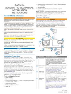
1 KDR Reactor Installation InstructionsKDR Reactor Installation GuideWhen installing the KDR Line Reactors on a Variable Frequency Drive (VFD), please use the following guidelines when wiring the unit:The KDR Line/Load Reactor is a 3-phase device and should be wired in series and positioned on the input or output side of the Terminal Block connectors will be marked. A1, B1, and C1 are the input terminals where the 3 phases of incoming power are to be wired. As a result, A2, B2, and C2 are the output terminals. Units with copper bus or ring lug terminals are not marked. In these cases, either the upper terminals or lower terminals can be used as the input terminals as long as the selection is consistent. Please see website for terminal drawings. Wiring: Only use 75 C copper conductors unless the wire connector is marked for Al/Cu, then the use of aluminum wire is recommends that these reactors be wired and located as close to the VFD as possible to have the greatest success in protecting sensitive standard 40 C ambient or less installations, a clearance of 3 inches on all sides of the reactors and its enclosure is recommended for assisting in heat dissipation and ample wire bending space.
2 This Reactor should only be installed and wired by personnel trained and familiar with local codes, NEC Article 110, and/or UL reactors are designed to be floor-mounted or wall-mounted. Large open-style devices should be panel mounted by incorporating a bracket that would act as a shelf to support the Reactor and/or enclosure. When installing an open style device in an existing enclosure, the Reactor should be mounted in the lower half of the cabinet to prevent hot spots or pockets of heat. Reactors with ducts are designed to be mounted vertically for proper cooling and maximum air Wiring DiagramsSingle-phase applications are acceptable, however, it is important to size the unit based on the single-phase Full Load Amperage of the VFD. The input and output connections should be on terminals A and C to ensure proper performance. For single-phase applications, use coils A and C.
3 Isolate terminals B1 and B2. 3-Phase, 690/600 Volt Class as marked UL Listed (cULus) or UL Recognized (cURus) and CSA listed (CSA) as marked CE Marked Current-rated device 200% rated current for 3 minutes Ambient Temperature: 40 /50 C as markedProduct SpecificationsFor more information on TCI line reactors, including drawings and schematics, visit: product support, please contact our TCI Technical Support N10611 Grant Drive Germantown, WI 53022Ph: 800-TCI-8282 | Part # 30895 C1A1B1*L1L3L2C2A2B2*VFD/ControllerLine Reactor SchematicKDR Reactor Lug KitsFigure 5 Figure 4 Figure 3 Figure 2 Figure 1 Warning Disconnect all power before working on the equipment. Do not attempt any work on a powered Reactor . The Reactor , VFD, motor, and other connected equipment must be properly grounded. The VFD terminals and connected cables are at a dangerously high voltage when power is applied to the VFD, regardless of motor operation.
4 All electrical connections must be re-torqued Part NumberDIN Rail KitKDRMA xxxxxxxDR01 KDRAA xxxxxxxDR02 KDRA xxxxxxxDR02 KDRB xxxxxxxDR02 DIN Rail KitsFull listing available at