Transcription of Kitchen Ventilation Systems: Part 2 Providing Adequate ...
1 1 Kitchen Ventilation Systems: part 2 Providing Adequate makeup Air The Pennsylvania Housing Research Center Builder Brief: April 2012 Anthony C. Jellen, PE & Brian M. Wolfgang, EIT, Michael A. Turns, MS INTRODUCTION The first Builder Brief of this two- part series discussed the relationship between Kitchen exhaust rates, house tightness, and house depressurization. That brief also provided an overview of the health and safety hazards associated with house depressurization and the presence of combustion appliances. In this brief, we provide design guidance for introducing makeup air for a residential Kitchen exhaust system using three common techniques: (1) engineered openings, (2) HVAC-integrated air systems, and (3) dedicated makeup air units.
2 We will also discuss common design practices for meeting the interlocking and closure requirements of the 2009 International Residential Code (IRC) Section PROPER RANGE EXHAUST SELECTION The objective of a Kitchen range exhaust system is to capture moisture and airborne contaminants created during cooking, and vent them to the outside. The selection of an exhaust system is largely dependent on the size and type of range, and its intended use. Wall mounted hoods are the most common exhaust system used in the residential Kitchen ; however, island canopy hoods and downdraft systems have risen in popularity in recent years. The goal of an exhaust system specifier should be to provide an Adequate , but not excessive, amount of exhaust without jeopardizing occupant safety or comfort.
3 First, a homeowner or homebuyer should assess their cooking habits and select appliances based on need rather than a bigger is better mentality. Larger appliances demand more power and require larger exhaust systems leading to higher operation costs, and increased risk of house depressurization and associated hazards. In addition, every cubic foot of exhausted air is a cubic foot of makeup air that must be heated or cooled at the homeowner s expense. The required exhaust rate for standard, low-powered, residential Kitchen ranges is typically specified per linear foot of range. Table 1 shows recommended exhaust rate per linear foot (LF), according to the Home Ventilating Institute (HVI). Table 1. HVI recommended and minimum Ventilation rates for Kitchen range hoods.
4 Kitchens that contain high-powered, commercial-style cooking equipment will require a higher exhaust rate. The installer should always check the equipment specifications for exhaust system recommendations. If no information is available, equipment should be classified by type, application and power consumption, and sized in accordance with the ASHRAE Handbook (HVAC Applications section), or other reputable source. makeup AIR REQUIREMENTS Once the exhaust rate is specified, the designer can determine the need for makeup air. As discussed in part 1 of this Builder Brief series, Section of the 2009 IRC requires makeup air at a rate roughly equal to the exhaust rate for systems capable of exceeding 400 CFM. That brief demonstrated that LOCATION Rec.
5 Vent. Rate per LF of Range Min. Vent. Rate per LF of Range Wall 100 CFM 40 CFM Island 150 CFM 50 CFM 2 the 400 CFM threshold, although seemingly arbitrary, is appropriate for tight to moderately tight residential enclosures. Figure 4 in part 1, shows that the potential for depressurization exists at almost any exhaust rate; therefore, it is prudent for a designer to conduct some type of risk assessment for all installations. See part 1 of this Builder Brief series, or ASTM E1998, Standard Guide for Assessing Depressurization Induced Backdrafting and Spillage from Vented Combustion Appliances. INTRODUCING makeup AIR Properly introducing makeup air is essential to ensuring a safe, comfortable, and efficient home. Improperly specified makeup air systems can lead to uncomfortable drafts, overstressed HVAC equipment, mold, and house depressurization.
6 An ill-conceived exhaust and makeup air system design can be expensive as well as non-functional. To maintain occupant comfort, most design guidance recommends Providing a makeup air supply temperature within 10 degrees F of the room temperature. For example, if a house is maintained at 70 degrees F in the wintertime, the makeup air should be provided at a supply temperature of no less than 60 degrees F. Design considerations for makeup air systems that exceed supply rates of 400 CFM are similar to that of a commercial Kitchen or industrial exhaust system . Thus, it is highly recommended that a HVAC expert be involved in the design process. Significant quantities of makeup air will increase loads placed on the central HVAC system .
7 The HVAC system or building enclosure will likely require modification to function efficiently with the newly introduced makeup air. makeup air can be introduced in many ways with varying degrees of effectiveness. The two most common methods are engineered openings and mechanical systems. Engineered openings in the enclosure allow air to be drawn into the house as interior pressure becomes increasingly negative. The effects are hard to predict and highly dependent on the location of the opening and connectivity of rooms within the house. Mechanical systems introduce makeup air into the house by a fan, where it can be routed directly to the Kitchen , or drawn into the central HVAC system and distributed throughout the house.
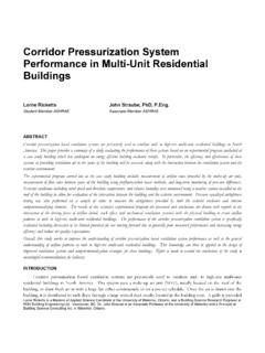
8 When properly installed, a fan-assisted solution should eliminate any adverse pressure effects created by the exhaust system . Figure 1 illustrates the effects of both methods on building pressurization and the neutral pressure plane. Figure 1. Comparison of air movement in a house with an engineered opening (Scenario #3) versus a house with fan-assisted a makeup air system (Scenario #4). In Scenario #3, the neutral pressure plane rises, and the level of house depressurization is less predictable. In Scenario #4, pressures in the house mirror those when no exhaust or makeup air systems are installed (natural conditions). ENGINEERED OPENINGS An engineered opening is an intentional opening placed in the enclosure for the purposes of transferring air between the interior and exterior of a building.
9 An opening could be as simple as a hole placed through an exterior wall, or may include ductwork to a remote space such as the Kitchen . Figure 1 shows a typical configuration for an engineered opening that supplies makeup air directly into the Kitchen . Providing one or more engineered openings in the enclosure is a simple and inexpensive technique to introduce makeup air. The effects are similar to that Y CFM X CFM FF X CFM X CFM NPP NPP F #3 #4 3 Figure 2. Typical engineered opening. The engineered opening in this diagram allows makeup air for a range hood to enter the house into the same room that the exhaust air leaves. This will help to alleviate negative pressure that may result from range hood operation. of opening a door or window. Typically a damper is incorporated into the opening design to minimize heating and cooling costs and to ensure airflow only during times of depressurization or exhaust operation.
10 Airflow through engineered openings depends primarily on the area of the opening and pressure difference across the opening. The pressure differential depends on all the factors discussed in part 1 of this series (wind, stack effect, and HVAC equipment). Table 2, which is derived from Equation 36 of Chapter 16 in the 2009 ASHRAE Handbook of Fundamentals, shows estimates of airflow through typical opening sizes (diameter) at various pressure differentials. Note that engineered openings only make sense for small amounts of makeup air. Pressures of 3 Pa or greater create a risk of backdrafting fireplaces and certain combustion appliances. Table 2. Airflow through an engineered opening. Pressure (Pa) Airflow (CFM)