Transcription of L-2 TB ET EE NPTEL
1 Module 1. Introduction Version 2 EE IIT, Kharagpur Lesson 2. generation , Transmission and Distribution of Electric Power an Overview Version 2 EE IIT, Kharagpur Contents 2 generation , transmission and distribution of electric power 2. Goals of the lesson .. 4. Introduction .. 4. Basic idea of generation .. 4. Changeover from to .. 5. generator 5. Thermal, hyddel & nuclear power stations 6. Thermal plant 7. Hydel plants .. 7. Nuclear plants 8. Transmission of power .. 10. Single line representation of power system .. 13. Distribution system 14. Conclusion . 15. Answer the following 16. Version 2 EE IIT, Kharagpur Chapter 2. generation , Transmission and Distribution of Electric Power (Lesson-2). Goals of the lesson After going through the lesson you shall get a broad idea of the following: 1. Different methods of generating electrical power. 2. Issues involved in transporting this power to different types of consumers located generally at far off places from the generating stations.
2 3. Necessity of substations to cater power to consumers at various voltage levels. Introduction In this lesson a brief idea of a modern power system is outlined. Emphasis is given to create a clear mental picture of a power system to a beginner of the course Electrical Technology. As consumers, we use electricity for various purposes such as: 1. Lighting, heating, cooling and other domestic electrical appliances used in home. 2. Street lighting, flood lighting of sporting arena, office building lighting, powering PCs etc. 3. Irrigating vast agricultural lands using pumps and operating cold storages for various agricultural products. 4. Running motors, furnaces of various kinds, in industries. 5. Running locomotives (electric trains) of railways. The list above is obviously not exhaustive and could be expanded and categorized in detail further. The point is, without electricity, modern day life will simply come to a stop.
3 In fact, the advancement of a country is measured by the index per capita consumption of electricity more it is more advanced the country is. Basic idea of generation Prior to the discovery of Faraday's Laws of electromagnetic discussion, electrical power was available from batteries with limited voltage and current levels. Although complicated in construction, generators were developed first to generate power in bulk. However, due to limitation of the machine to generate voltage beyond few hundred volts, it was not economical to transmit large amount of power over a long distance. For a given amount of power, the current magnitude (I = P/V), hence section of the copper conductor will be large. Thus generation , transmission and distribution of power were restricted to area of few Version 2 EE IIT, Kharagpur kilometer radius with no interconnections between generating plants.
4 Therefore, area specific generating stations along with its distribution networks had to be used. Changeover from to In later half of eighties, in nineteenth century, it was proposed to have a power system with 3- phase, 50 Hz generation , transmission and distribution networks. Once system was adopted, transmission of large power (MW) at higher transmission voltage become a reality by using transformers. Level of voltage could be changed virtually to any other desired level with transformers which was hitherto impossible with system. Nicola Tesla suggested that constructionally simpler electrical motors (induction motors, without the complexity of commutator segments of motors) operating from 3-phase supply could be manufactured. In fact, his arguments in favor of supply system own the debate on switching over from to system. generator power can be generated as a single phase or as a balanced poly-phase system.
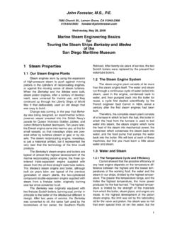
5 However, it was found that 3-phase power generation at 50 Hz will be economical and most suitable. Present day three phase generators, used to generate 3-phase power are called alternators (synchronous generators). An alternator has a balanced three phase winding on the stator and called the armature. The three coils are so placed in space that there axes are mutually 120 apart as shown in figure From the terminals of the armature, 3-phase power is obtained. Rotor houses a field coil and excited by The field coil produces flux and electromagnetic poles on the rotor surface. If the rotor is driven by an external agency, the flux linkages with three stator coils becomes sinusoidal function of time and sinusoidal voltage is induced in them. However, the induced voltages in the three coils (or phases) will differ in phase by 120 because the present value of flux linkage with R-phase coil will take place after 120 with Y-phase coil and further 120 after, with B-phase coil.
6 A salient pole alternator has projected poles as shown in figure (a). It has non uniform air gap and is generally used where speed is low. On the other hand a non salient pole alternator has uniform air gap (figure (b)) and used when speed is high. R R. Driven at n rps by Driven at n rps by prime mover prime mover Field N. S. coil Field coil N. S. B Y B Y. (a) Salient pole generator (b) Non salient pole generator Figure : 3-phase generators. Version 2 EE IIT, Kharagpur Frequency, voltage & interconnected system The frequency of the generated emf for a p polar generator is given by f = 2p n where n is speed p of the generator in rps or f = 120 n when n is in rpm. Frequency of the generated voltage is standardized to 50 HZ in our country and several European countries. In USA and Canada it is 60 Hz. The following table gives the rpm at which the generators with different number of poles are to be driven in order to generate 50 Hz voltage.
7 Number of poles of Generator 2 4 6 8 10. rpm at which generator to be driven 3000 1500 1000 750 600. A modern power station has more than one generator and these generators are connected in parallel. Also there exist a large number of power stations spread over a region or a country. A. regional power grid is created by interconnecting these stations through transmission lines. In other words, all the generators of different power stations, in a grid are in effect connected in parallel. One of the advantages of interconnection is obvious; suppose due to technical problem the generation of a plant becomes nil or less then, a portion of the demand of power in that area still can be made from the other power stations connected to the grid. One can thus avoid complete shut down of power in an area in case of technical problem in a particular station. It can be shown that in an interconnected system, with more number of generators connected in parallel, the system voltage and frequency tend to fixed values irrespective of degree of loading present in the system.
8 This is another welcome advantage of inter connected system. Inter connected system however, is to be controlled and monitored carefully as they may give rise to instability leading to collapse of the system. All electrical appliances (fans, refrigerator, TV etc.) to be connected to supply are therefore designed for a supply frequency of 50 Hz. Frequency is one of the parameters which decides the quality of the supply. It is the responsibility of electric supply company to see that frequency is maintained close to 50 Hz at the consumer premises. It was pointed out earlier that a maximum of few hundreds of volts (say about 600 to 700 V). could be developed in a generator, the limitation is imposed primarily due to presence of commutator segments. In absence of commutators, present day generated voltage in alternator is much higher, typically around 10 kV to 15 kV. It can be shown that rms voltage induced in a coil is proportional to and n , Ecoil n where is the flux per pole and n is speed of the alternator.
9 This can be justified by intuition as well: we know that mere rotating a coil in absence of magnetic flux ( ) is not going to induce any voltage. Also presence of flux without any rotation will fail to induce any voltage as you require rate of change of flux linkage in a coil. To control the induced voltage one has to control the field current as speed of the alternator gets fixed by frequency constrain. Thermal, hyddel & nuclear power stations In this section we briefly outline the basics of the three most widely found generating stations . thermal, hydel and nuclear plants in our country and elsewhere. Version 2 EE IIT, Kharagpur Thermal plant We have seen in the previous section that to generate voltage at 50 Hz we have to run the generator at some fixed rpm by some external agency. A turbine is used to rotate the generator. Turbine may be of two types, namely steam turbine and water turbine.
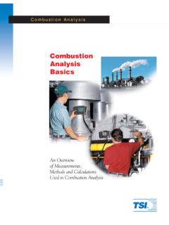
10 In a thermal power station coal is burnt to produce steam which in turn, drives the steam turbine hence the generator (turbo set). In figure the elementary features of a thermal power plant is shown. In a thermal power plant coil is burnt to produce high temperature and high pressure steam in a boiler. The steam is passed through a steam turbine to produce rotational motion. The generator, mechanically coupled to the turbine, thus rotates producing electricity. Chemical energy stored in coal after a couple of transformations produces electrical energy at the generator terminals as depicted in the figure. Thus proximity of a generating station nearer to a coal reserve and water sources will be most economical as the cost of transporting coal gets reduced. In our country coal is available in abundance and naturally thermal power plants are most popular. However, these plants pollute the atmosphere because of burning of coals.