Transcription of Lab 1.3.1: Review of Concepts from Exploration 1
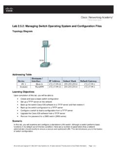
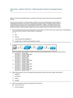
1 Lab : Review of Concepts from Exploration 1 Topology Diagram Learning Objectives Upon completion of this lab, you will be able to: Create a logical topology given network requirements Create subnets to meet host requirements Configure the physical topology Configure the logical topology Verify network connectivity Configure and verify passwords Scenario In this lab, you will design and configure a small routed network and verify connectivity across multiple network devices. This requires creating and assigning two subnetwork blocks, connecting hosts and network devices, and configuring host computers and one cisco router for basic network connectivity. Switch1 has a default configuration and does not require additional configuration.
2 You will use common commands to test and document the network. The zero subnet is used. All contents are Copyright 1992 2007 cisco Systems, Inc. All rights reserved. This document is cisco Public Information. Page 1 of 12 ccna Exploration LAN Switching and Wireless: LAN Design Lab : Review of Exploration 1 Task 1: Design a Logical LAN Topology Step 1: Design an IP addressing scheme. Given the IP address block of /24, design an IP addressing scheme that satisfies the following requirements: Subnet Number of Hosts Subnet A 110 Subnet B 54 The 0 subnet is used. No subnet calculators may be used. Create the smallest possible subnets that satisfy the requirements for hosts. Assign the first usable subnet to Subnet A. Subnet A Specification Student Input Number of bits in the subnet IP mask (binary) New IP mask (decimal) Maximum number of usable subnets (including the 0 subnet) Number of usable hosts per subnet IP subnetwork address First IP host address Last IP host address Subnet B Specification Student Input Number of bits in the subnet IP mask (binary) New IP mask (decimal) Maximum number of usable subnets (including the 0 subnet)
3 Number of usable hosts per subnet IP network address First IP host address Last IP host address Host computers will use the first usable IP address in the subnet. The network router will use the last usable IP address in the subnet. Step 2: Write down the IP address information for each device. Device IP address Mask Gateway Host1 Router1-Fa0/0 Host2 Router1-Fa0/1 Table 1. IP Address Assignments All contents are Copyright 1992 2007 cisco Systems, Inc. All rights reserved. This document is cisco Public Information. Page 2 of 12 ccna Exploration LAN Switching and Wireless: LAN Design Lab : Review of Exploration 1 Before proceeding, verify your IP addresses with the instructor.
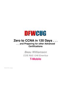
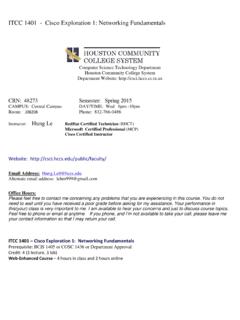
4 Task 2: Configure the Physical Topology Step 1: Cable the network. Refer to the figure and table below for the necessary cables. Cabling Cable Type LAN cable between Host1 and Router1 Fa0/0 Crossover LAN cable between Switch1 and Router1 Fa0/1 Straight-through LAN cable between Switch1 and Host2 Straight-through Console cable between Host1 and Router1 Rollover Figure 1. Cabling the network Step 2: Physically connect lab devices. Cable the network devices as shown in Figure 1. Turn power on to all devices if it is not already on. Step 3: Inspect the network connections. Verify the connections visually.
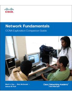
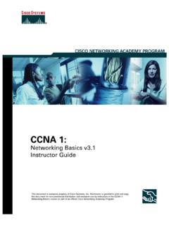
5 Task 3: Configure the Logical Topology Step 1: Configure the host computers. Configure the static IP address, subnet mask, and gateway for each host computer. Note: The following directions are for Windows XP. To configure hosts using other operating systems, refer to the operating system manual. To configure the host, go to Start > Control Panel > Network Connections > Local Area Connection. In the Local Area Connection Properties window, select Internet Protocol (TCP/IP) and click the Properties button. All contents are Copyright 1992 2007 cisco Systems, Inc. All rights reserved. This document is cisco Public Information. Page 3 of 12 ccna Exploration LAN Switching and Wireless: LAN Design Lab : Review of Exploration 1 Figure 2.
6 Setting Properties for Internet Protocol (TCP/IP) In the TCP/IP Properties dialog box for each host, enter the IP address, network mask, and the gateway from Table 1. After configuring each host computer, open a command window on the host by selecting Start > Run. When prompted to type the name of a program, enter cmd in the text box. From the command window, display and verify the host network settings with the ipconfig /all command. The settings should match those in the tables below: Host1 Network Configuration IP address Subnet mask Default gateway Host2 Network Configuration IP address Subnet mask Default gateway Are the host settings in agreement with the tables? _____ If not, reconfigure as necessary. All contents are Copyright 1992 2007 cisco Systems, Inc.
7 All rights reserved. This document is cisco Public Information. Page 4 of 12 ccna Exploration LAN Switching and Wireless: LAN Design Lab : Review of Exploration 1 Step 2: Configure Router1. From Host1, connect to the console of Router 1 and establish a console session. Directions for creating a console connection using HyperTerminal are in Appendix 2. From the router console, configure the following: Task Specification Router name Router1 Encrypted privileged exec password cisco Console access password class Telnet access password class Router1 interface Fa0/0 Set the description Set the Layer 3 address Router1 interface Fa0/1 Set the description Set the Layer 3 address Enter the following commands on the router: Router>enable Router#config term Enter configuration commands, one per line.
8 End with CNTL/Z. Router(config)#hostname Router1 Router1(config)#enable secret class Router1(config)#line console 0 Router1(config-line)#password cisco Router1(config-line)#login Router1(config-line)#line vty 0 4 Router1(config-line)#password cisco Router1(config-line)#login Router1(config-lineinterface fa0/0)# Router1(config-if)#ip address Router1(config-if)#no shutdown Router1(config-if)#description connection to host1 Router1(config-if)#interface fa0/1 Router1(config-if)#description connection to switch1 Router1(config-if)#ip address Router1(config-if)#no shutdown Router1(config-if)#end Router1# Task 4: Verify Network Connectivity Step 1: Use the ping command to verify network connectivity. You can verify network connectivity using the ping command.
9 All contents are Copyright 1992 2007 cisco Systems, Inc. All rights reserved. This document is cisco Public Information. Page 5 of 12 ccna Exploration LAN Switching and Wireless: LAN Design Lab : Review of Exploration 1 Note: If pings to the host computers fail, temporarily disable the computer firewall and retest. To disable a Windows firewall, select Start > Control Panel > Windows Firewall, select OFF, and then OK. Use the following table to verify connectivity with each network device. Take corrective action to establish connectivity if a test fails. From To IP Address Ping Results Host1 NIC IP address Host1 Router1, Fa0/0 Host1 Router1, Fa0/1 Host1 Host2 Host2 NIC IP address Host2 Router1, Fa0/1 Host2 Router1, Fa0/0 Host2 Host1 In addition to the ping command, what other Windows command is useful in displaying network delay and breaks in the path to the destination?
10 _____ Task 5: Verify Passwords Step 1: Telnet to the router from Host2 and verify the Telnet password. You should be able to telnet to either Fast Ethernet interface of the router. In a command window on Host 2, type: telnet When you are prompted for the Telnet password, type cisco and press Enter. Was the telnet successful? _____ Step 2: Verify that the enable secret password has been set. From the Telnet session, enter privilege exec mode and verify it is password protected: Router>enable Were you prompted for the enable secret password? _____ Step 3: Verify that the console is password protected. Terminate and then re-establish the console connection from Host1 to the router to verify that the console is password protected. Depending on the Telnet client that you are using, the session can usually be terminated with Ctrl-].