Transcription of Lab 3.5.1: Basic VLAN Configuration - ut
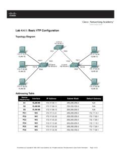
1 All contents are Copyright 1992 2007 Cisco Systems, Inc. All rights reserved. This document is Cisco Public Information. Page 1 of 6 Lab : Basic VLAN Configuration Topology Diagram Addressing Table Device (Hostname) Interface IP Address Subnet Mask Default Gateway S1 VLAN 99 N/A S2 VLAN 99 N/A S3 VLAN 99 N/A PC1 NIC PC2 NIC PC3 NIC PC4 NIC PC5 NIC PC6 NIC Initial Port Assignments (Switches 2 and 3) Ports Assignment Network Fa0/1 0/5 Trunks (Native VLAN 99) /24 Fa0/6 0/10 VLAN 30 Guest (Default)
2 /24 Fa0/11 0/17 VLAN 10 Faculty/Staff /24 Fa0/18 0/24 VLAN 20 Students /24 CCNA Exploration LAN Switching and Wireless: VLANs Lab : Basic VLAN Configuration All contents are Copyright 1992 2007 Cisco Systems, Inc. All rights reserved. This document is Cisco Public Information. Page 2 of 6 Learning Objectives Upon completion of this lab, you will be able to: Cable a network according to the topology diagram Erase the startup Configuration and reload a switch to the default state Perform Basic Configuration tasks on a switch Create VLANs Assign switch ports to a VLAN Add, move, and change ports Verify VLAN Configuration Enable trunking on inter-switch connections Verify trunk Configuration Save the VLAN Configuration Task 1.
3 Prepare the Network Step 1: Cable a network that is similar to the one in the topology diagram. You can use any current switch in your lab as long as it has the required interfaces shown in the topology. Note: If you use 2900 or 2950 switches, the outputs may appear different. Also, certain commands may be different or unavailable. Step 2: Clear any existing configurations on the switches, and initialize all ports in the shutdown state. If necessary, refer to Lab , Appendix 1, for the procedure to clear switch configurations.
4 It is a good practice to disable any unused ports on the switches by putting them in shutdown. Disable all ports on the switches: Switch#config term Switch(config)#interface range fa0/1-24 Switch(config-if-range)#shutdown Switch(config-if-range)#interface range gi0/1-2 Switch(config-if-range)#shutdown Task 2: Perform Basic Switch Configurations Step 1: Configure the switches according to the following guidelines. Configure the switch hostname. Disable DNS lookup. Configure an EXEC mode password of class. Configure a password of cisco for console connections.
5 Configure a password of cisco for vty connections. Step 2: Re-enable the user ports on S2 and S3. S2(config)#interface range fa0/6, fa0/11, fa0/18 S2(config-if-range)#switchport mode access CCNA Exploration LAN Switching and Wireless: VLANs Lab : Basic VLAN Configuration All contents are Copyright 1992 2007 Cisco Systems, Inc. All rights reserved. This document is Cisco Public Information. Page 3 of 6 S2(config-if-range)#no shutdown S3(config)#interface range fa0/6, fa0/11, fa0/18 S3(config-if-range)#switchport mode access S3(config-if-range)#no shutdown Task 3: Configure and Activate Ethernet Interfaces Step 1: Configure the PCs.
6 You can complete this lab using only two PCs by simply changing the IP addressing for the two PCs specific to a test you want to conduct. For example, if you want to test connectivity between PC1 and PC2, then configure the IP addresses for those PCs by referring to the addressing table at the beginning of the lab. Alternatively, you can configure all six PCs with the IP addresses and default gateways. Task 4: Configure VLANs on the Switch Step 1: Create VLANs on switch S1. Use the vlan vlan-id command in global Configuration mode to add a VLAN to switch S1.
7 There are four VLANS configured for this lab: VLAN 10 (faculty/staff); VLAN 20 (students); VLAN 30 (guest); and VLAN 99 (management). After you create the VLAN, you will be in vlan Configuration mode, where you can assign a name to the VLAN with the name vlan name command. S1(config)#vlan 10 S1(config-vlan)#name faculty/staff S1(config-vlan)#vlan 20 S1(config-vlan)#name students S1(config-vlan)#vlan 30 S1(config-vlan)#name guest S1(config-vlan)#vlan 99 S1(config-vlan)#name management S1(config-vlan)#end S1# Step 2: Verify that the VLANs have been created on S1.
8 Use the show vlan brief command to verify that the VLANs have been created. S1#show vlan brief VLAN Name Status Ports ---- ------------------------------- --------- ----------------------------- 1 default active Fa0/1, Fa0/2, Fa0/4, Fa0/5 Fa0/6, Fa0/7, Fa0/8, Fa0/9 Fa0/10, Fa0/11, Fa0/12, Fa0/13 Fa0/14, Fa0/15, Fa0/16, Fa0/17 Fa0/18, Fa0/19, Fa0/20.
9 Fa0/21 Fa0/22, Fa0/23, Fa0/24, Gi0/1 Gi0/2 10 faculty/staff active 20 students active 30 guest active 99 management active CCNA Exploration LAN Switching and Wireless: VLANs Lab : Basic VLAN Configuration All contents are Copyright 1992 2007 Cisco Systems, Inc. All rights reserved. This document is Cisco Public Information. Page 4 of 6 Step 3: Configure and name VLANs on switches S2 and S3.
10 Create and name VLANs 10, 20, 30, and 99 on S2 and S3 using the commands from Step 1. Verify the correct Configuration with the show vlan brief command. What ports are currently assigned to the four VLANs you have created? _____ Step 4: Assign switch ports to VLANs on S2 and S3. Refer to the port assignment table on page 1. Ports are assigned to VLANs in interface Configuration mode, using the switchport access vlan vlan-id command. You can assign each port individually or you can use the interface range command to simplify this task, as shown here.