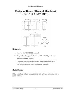
Transcription of LATERALLY RESTRAINED BEAMS
1 LATERALLY RESTRAINED BEAMS LATERALLY RESTRAINED BEAMS INTRODUCTION BEAMS are structural members frequently used to carry loads that are transverse to their longitudinal axis. They transfer loads primarily by bending and shear. In a rectangular building frame, BEAMS that span between adjacent columns are called main or primary BEAMS /girders . BEAMS , which are used to transmit the floor loading to the main BEAMS between columns, are called secondary BEAMS /joists . As far as the structural steel framing in buildings is concerned, it is sufficient to consider only the bending effects for BEAMS , as torsion is not generally predominant. For a beam (loaded predominantly by flexure) two essential requirements must be met to develop its full moment capacity: 1. The elements of the beam ( flange and web) should not buckle locally and 2.
2 The beam as a whole should not buckle LATERALLY . To ensure that the first condition is met, the cross sections of the flange and the web chosen must be plastic or compact . (These definitions are explained in the chapter on Local buckling and also in later part of this chapter). If the beam is required to have significant ductility, plastic sections must invariably be used. To avoid the lateral buckling referred to under the second condition, restraints are provided to the beam in the plane of the compression flange, and hence such BEAMS are called LATERALLY RESTRAINED BEAMS . In many steel structures, especially in buildings, BEAMS carry floor decks on top of them, and these floor decks provide restraint to the compression flange. In the absence of any such restraints, and in case the lateral buckling of BEAMS is not accounted for in design , the designer has to provide adequate lateral supports to the compression flange.
3 In this chapter we are concerned with LATERALLY RESTRAINED BEAMS , in other words BEAMS which have adequate lateral support to the compression flange. BEAMS , which buckle LATERALLY , are covered in the next chapter. BEHAVIOUR OF STEEL BEAMS LATERALLY stable steel BEAMS can fail only by (a) flexure (b) shear or (c) bearing, assuming that local buckling of slender components does not occur. These three conditions are the criteria for Limit State of collapse for steel BEAMS . Steel BEAMS would also become unserviceable due to excessive deflection and this is classified as a limit state of serviceability. In the following sections, we review the fundamentals of these limit states. Flexural behaviour of steel BEAMS It is important to recognise that only plastic sections can be used in plastic design of frames , where moment redistribution is required throughout the frame.
4 Plastic analysis of the cross section is confined to the assessment of the behaviour of the cross section at the instant of collapse. These two terms are not to be confused for each other. Copyright reserved Version II 9 - 9 LATERALLY RESTRAINED BEAMS If a flexural member is progressively loaded, it deflects and the curvature of such bending varies along its length. Initially the beam is elastic throughout its length. Let us consider a small portion of the beam at a point A as shown in (a) where the curvature is . If we consider a small segment of the beam at A [ (b)], then the variation of the strain across the depth of the member could be found out geometrically as z= (1) MDeflected shape A dx max z h c NA dx MCurvature =1/ (a) (b) Curvature of bending From , the strain at any fibre is proportional to its distance z from the neutral axis.
5 This is obtained from the assumption that plane sections which are normal to the longitudinal axis before bending, remains plane and normal even after bending. For each Stress 1 strain1 2 y2 =33 4 4 fyPlastic range Elastic range f Idealised stress strain curve Idealised elasto- plastic stress- strain curve for steel Version II 9 - RESTRAINED BEAMS strain one can read off the corresponding stress f from the idealised stress-strain curve for steel shown in Fig. 2. (The idealised stress strain curve neglects the strain-hardening portion for all practical purposes). We choose four points 1, 2, 3, 4 on the stress-strain curve (Fig. 2) for further discussion and see how these four points are used when a simply supported beam is subjected to a mid point load.
6 Elastic flexural behaviour Consider the point (1) in in which the strain 1max = which is less than the yield strain y . At this stage, as seen from Figures 2 and 3, the stress is directly proportional to strain. Hence from elementary Strength of Materials, the corresponding moment of resistance (Mc ) is given by cIfM1c= (2) f1<fyf2=fy 1< y 2= y 1 2 Strain and stress distributions in the elastic range where f1 is the extreme fibre stress, I is the moment of inertia and c is the extreme fibre distance from the neutral axis. The term Ze = I/c is the elastic section modulus which is a geometric property of the section. Hence can be rewritten in terms of elastic section modulus as ecZfM1= (3) Yield and plastic moment capacities Now let us consider the point (2) in Fig.
7 2. The extreme fibre strain equals yield strain == and also the stress f2 = fy. Where, fy is the yield stress. Up to this stage, as shown in Fig. 3, the stress and strain are proportional to each other since the extreme fibre of the beam is stressed within the elastic range. The corresponding moment, (My), is just sufficient to cause yield in the extreme fibres and is given by Version II 9 - RESTRAINED BEAMS eyyZfM= (4) Where My is called the yield moment , the moment which just causes the extreme fibres to yield. It is evident from Fig. 5(b) that once the extreme fibre stresses attain yield stress they no longer take any additional stresses. 3> yf3=fyf3<fyStrain Stress B3 fyT d td0d0ztzcAtAc4 zt zcf4=fy 4>> y Strain Stress Fig. 4 Strain and stress distributions in plastic range When the load and hence the moment is further increased, the outermost fibre strain max near mid span of the beam ( point of maximum bending moment) would attain a value say,y3 > and this is identified as point (3) in Fig.
8 2. At this stage the strain is in the plastic stage, but extreme fibre stress still equals yield stress fy. We also note that the stresses have been redistributed to the inner fibres towards the neutral axis and these fibres gradually attain a stress equal to fy. This is shown in The remaining portion of the beam in the vicinity of the neutral axis is still elastic. At this stage the moment capacity is calculated by considering both the plastic portion and the elastic core as, Version II 9 - RESTRAINED BEAMS 321444344421coreElasticyPlastictcyctdfzz tdBTfM6)()(20+++= (5) 1243fyfyfy(b) Plasticization of cross section <fyMyMPM (a) Bending Moment diagram 214321(c) Curvature =M/EI Diagram 4 Curvature max at collapse 3 BM diagram and spread of plasticity across the thickness of the beam Upon further loading, the outer fibre strain increases rapidly and attains a stage shown as point (4) in At this stage the elastic core in the immediate vicinity of the neutral axis becomes negligible due to the spread of plasticity into the fibres near the neutral Version II 9 - RESTRAINED BEAMS axis.
9 It is seen from Fig. 5(c) that the curvature of the beam (which was proportional to bending moment earlier) increases far more rapidly compared to the previous rate of increase, when the bending moment exceeds the yield moment value M y. When the entire cross section of the beam gets fully plastified, the curvature become infinity as shown in Fig. 5(c). shows such a cross-section, which is fully plastified. This also is shown in where the two yield zones have merged at the neutral axis. When the entire beam cross section becomes plastic, it resists any further rotation under constant moment. At this stage the beam is said to have developed a plastic hinge . In view of this rotation, deflections become very large and the beam exhibits a kink at the plastic hinge as shown in Fig 7.
10 The magnitude of the bending moment, at which a plastic hinge is formed, is known as the plastic moment Mp . The moment- curvature relation of the cross section of the beam , at the point of maximum bending moment is shown in Fig. 6. The curvature increases enormously once the moment at the cross section reaches MP. The value of Mp could be easily determined by taking moment of the total tension and compression areas about the plastic neutral axis as )zz(2Af)zAzA(fTzCzMtcyttccytcp+=+=+= (6) as shown in , where Ac = area under compressive yield stress and At = area under tensile yield stress. Yield momentPlastic momentCurvature MP Moment M MY Fig. 6 Moment curvature characteristics of a simply supported beam Version II 9 - RESTRAINED BEAMS P 1234 Plastic Hinge Simply supported beam and its deflection at various stages In symmetrical sections the neutral axis coincides with the centroidal axis and this is not so in the case of unsymmetrical sections.