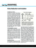
Transcription of LDO noise examined in detail - Texas Instruments
1 Analog Applications JournalHigh-Performance Analog Products 4Q 2012 Texas Instruments Incorporated14 LDO noise examined in detailIntroductionRequirements and expectations for telecommuni-cation systems continue to evolve as complexity and reliability of the communication channels continue to increase. These communication sys-tems rely heavily on high-performance, high-speed clocking and data-converter devices. The perform-ance of these devices is highly dependent on the quality of system power rails. A clock or converter IC simply cannot achieve top perform ance when powered by a dirty power supply. Just a small amount of noise on the power supply can cause dramatic negative effects on the perform ance. This article examines a basic LDO topology to find its dominant noise sources and suggests ways to minimize its output key parameter indicating the quality of a power supply is its noise output, which is com-monly referred by the RMS noise measurement or by the spectral noise density.
2 For the lowest RMS noise or the best spectral noise characteristics, a linear voltage regulator like a low-dropout voltage regulator (LDO) always has an advantage over a switching regulator. This makes it the power sup-ply of choice for noise -critical LDO topologyA simple linear voltage regulator consists of a basic control loop where a negative feedback is compared to an internal reference in order to pro-vide a constant voltage regardless of changes or perturbations in the input voltage, temperature, or load 1 shows a basic block diagram of an LDO regulator. The red arrow indicates the negative-feedback signal path. The output voltage, VOUT, is divided by feedback resistors R1 and R2 to provide the feedback voltage, VFB. VFB is compared to the reference voltage, VREF, at the negative input of the error amplifier to supply the gate-drive voltage, VGATE.
3 Finally, the error signal drives the output transistor, NFET, to regulate simplified analysis of noise begins with Figure 2. The blue arrow traces a subset of the loop repre-sented by a common amplifier variation known as a volt-age follower or power buffer. This voltage-follower circuit forces VOUT to follow VREF. VFB is the error signal referring to VREF. In steady state, VOUT is bigger than VREF, as described in Equation 1:By Masashi NogawaSenior Systems Engineer, Linear RegulatorsPower ManagementVINCOUTR1R2 VREFVGATE+ + NFETOUT Node(V)OUTFB Node(V)FBErrorAmpFigure 1. Negative-feedback loop of LDO OUTREFR1V1 V,R2 =+ (1)where 1 + R1/R2 is the gain that the error amplifier must have to obtain the steady-state output voltage (VOUT).
4 VINCOUTR1R2 VREFVGATE+ + NFETOUT Node(V)OUTFB Node(V)FBErrorAmpFigure 2. Reference-voltage buffering of LDOT exas Instruments Incorporated15 Analog Applications Journal4Q 2012 High-Performance Analog ProductsPower ManagementSuppose the voltage reference is not ideal and has an effective noise factor, VN(REF), on its DC output voltage (VREF). Assuming all circuit blocks in Figure 2 are ideal, VOUT becomes a function of the noise source. Equation 1 can be easily modi-fied to account for the noise source, as described in Equation 2:OUTN(OUT)REFN(REF)R1V V1 (VV),R2 +=+ + (2)where VN(OUT) is the independent noise contribu-tion to the output, expressed by Equation 3: N(OUT)N(REF)R1V1 VR2 =+ (3)From Equations 2 and 3, it s clear that a higher output voltage generates higher output noise .
5 The feedback resistors, R1 and R2, set (or adjust) the output voltage, thereby setting the output noise voltage. For this reason, many LDO devices char-acterize the noise performance as a function of out put voltage. For example, VN = 16 VRMS VOUT illustrates a standard form describing the output sources of LDO output- voltage noiseFor most typical LDO devices, a dominant source of output noise is the amplified reference noise in Equation 3. This is generally true even though the total output noise is device-dependent. Figure 3 is a complete block diagram showing each equivalent- noise source corresponding to its respective circuit element. Since any device with current flowing through it is a potential noise source, every single component in Figure 1 and Figure 2 is a noise 4 is redrawn from Figure 3 to include all equivalent- noise sources referenced at the OUT node.
6 The complete noise equation is N(OUT)N(AMP)N(FET)N(REF)N(R1)N(R2)R1VV V 1 R2(V V V). =+++ ++ (4)In most cases, because the reference-voltage block, or bandgap circuit, consists of many resistors, transistors, and capacitors, VN(REF) tends to dominate the last three noise sources in this equation where VN(REF) >> VN(R1) or VN(REF) >> VN(R2). Thus, Equation 4 can be simplified to N(OUT)N(AMP)N(FET)N(REF)R1VV V 1 VR2. =+++ (5)VINCOUTR1R2 VREFVN(REF)VN(R2)VN(R1)VN(FET)VN(AMP)VGA TE+ + NFETOUT Node(V)OUTFB Node(V)FBErrorAmpFigure 3. LDO topology with equivalent- noise sourcesVINCOUTR1R2 VREFVN(OUT)VGATE+ + NFETOUT Node(V)OUTFB Node(V)FBErrorAmpFigure 4. LDO topology with a consolidated noise sourceTexas Instruments Incorporated16 Analog Applications JournalHigh-Performance Analog Products 4Q 2012 Power ManagementFor higher-performance LDO devices, it is com-mon to add a noise -reduction (NR) pin to shunt reference noise to ground.
7 Figure 5 illustrates how the NR pin works to reduce noise . Since it is known that VN(REF) is the dominant output- noise source, an RC filter capacitor, CNR, is inserted be-tween the reference-voltage block (VREF) and the error amplifier to reduce this noise . This RC filter reduces the noise by an attenuation function of ()RC2p1G(f)1,1ff=<+ (6)where The amplified reference noise is therefore reduced to (1 + R1/R2) VN(REF) GRC, and Equation 5 then becomes N(OUT)N(AMP)N(FET)N(REF)RCR1VV V 1 R2V G. =+++ (7)In the real world, all control signal levels are frequency-dependent, including the noise signal. If the error amplifier has limited bandwidth, the high-frequency reference noise (VN(REF)) is fil-tered by the error amplifier in a way similar to using an RC filter.
8 But in reality an error amplifier tends to have a very wide bandwidth, so the LDO device has very good power-supply ripple rejection (PSRR), which is another key performance param-eter of high-performance LDOs. To satisfy this conflicting requirement, IC vendors settle on hav-ing a wide-bandwidth error amplifier for the best PSRR over less noise . This decision leads to using an NR pin function if low noise is also reference noise in a typical circuitAmplified reference noiseThe Texas Instruments (TI) TPS74401 LDO was used for testing and measurements. The common setup parameters are shown in Table 1. Please note that a soft-start capacitor, CSS, in the TPS74401 datasheet1 is referred to as a noise -reduction capacitor, CNR, in this article for easier , the effect of the amplifier gain was examined with a negligibly small CNR.
9 Figure 6 shows RMS noise versus output-voltage settings. As discussed earlier, the dominant noise source, VN(REF), is amplified by the ratio of the feed-back resistors R1 and R2. Equation 7 can be modified into the form of Equation 8: N(OUT)N(Other)N(REF)RCR1VV 1 VGR2, =++ (8)where VN(Other) is the sum of all other noise 1. Setup parametersVIN = VOUT(Target) + VIOUT = ACOUT = 10 FVOUT(Target)R1R21 + R1/R23 .3 V31 .25 k 10 k 4 .1251 .8 V12 .5 k 10 k 2 .251 .2 V5 k 10 k 1 .50 .8 V0 (short OUT node to FB node)Open circuit1 VINCOUTR1R2 VREFVN(REF)VN(R2)VN(R1)VN(FET)VN(AMP)VGA TE+ + NFETOUT Node(V)OUTCNRNR PinVREF1 RNRFB Node(V)FBErrorAmpFigure 5. LDO topology with reference- noise Voltage, V(V)OUTRMS noise ( V)RMSC= 1 pFC= 10 pF100 Hz to 100 kHzNRFFM easurementCurve FittingFigure 6.
10 RMS noise versus output voltageIf Equation 8 is fitted to a linear curve of the form y = ax + b as shown by the red dotted line in Figure 6, VN(REF) (the slope term) can be estimated as 19 VRMS, and VN(Other) (the y-intercept term) as VRMS. As explained Texas Instruments Incorporated17 Analog Applications Journal4Q 2012 High-Performance Analog ProductsPower Managementlater under Effect of the noise -reduction (NR) pin, the value of CNR was chosen as 1 pF to mini-mize the RC-filter effect to a negligible level, and GRC is treated as being equal to 1. In this situation, the basic assumption is that VN(REF) is the domi-nant noise that the minimum noise occurs when the OUT node is shorted to the FB node, making the amplifier gain (1 + R1/R2) equal to 1 (R1 = 0) in Equation 8.