Transcription of Let's Talk Transmission Lines
1 Let s Talk Transmission LinesDon t neglect one of the most important parts of your station!By Edward J. Farmer, AA6 ZMNo one wants to discuss Transmission Lines . Many hams would rather chew aluminum foil. After all, Transmission Lines are just the cables that link your radios to your antennas. You hook them up and get on the air. Who cares? Boring!Well, the subject may not have much sex appeal, but if you want to get maximum performance from your station, give me your attention for a couple of minutes. These Lines have a major influence on the results you ll achieve on the air.
2 A little extra knowledge will literally take you a long way!It s a Question of ImpedanceModern solid state radios expect a load impedance of 50 , resistive. We want to connect them to an antenna, the feed-point impedance of which can be anything. It depends on the antenna design, plus how and where it s installed. In general, the impedance is complex, meaning it has both resistive and reactive components. (Don t worry we ll discuss reactance in a moment.)Antenna ImpedanceEven though the electrical properties are distributed throughout the antenna, it s easier to think about a lumped impedance representing the load present at its feed point.
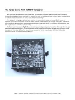
3 Two resistors in series with an inductor and capacitor is a useful model (see Figure 1).Figure 1 The radio, antenna and Transmission line . The object is to get as much power as possible from the radio into the antenna s radiation of the resistors is the desirable radiation resistance, which represents the useful work done by the antenna in converting your transmitter s output into radiation that spans states or continents! The other is the loss resistance resulting from the resistance of the wire and connections. (Now you know why you need good solder joints and sound mechanical connections on your antenna.)
4 Power consumed in the loss resistance does not increase the RF field it merely makes heat. The radiation resistance is usually the larger of the two, but in some designs, such as small loops, radiation resistance is so small that loss resistance becomes is the effect produced by the inductor and capacitor. The net effect can be capacitive or inductive depending on the frequency. An antenna is, after all, a distributed tuned circuit. At resonance, the capacitive reactance is canceled exactly by the inductive reactance and the net effect is simply that of the two resistors.
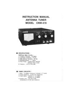
5 When the operating frequency is below resonance, the capacitive component dominates while above resonance the inductive component dominates. Put another way, wire antennas that are shorter than required for resonance are capacitive and antennas that are longer are inductive. Transmission - line ImpedanceJune QST: Let s Talk Transmission Lines - Page 1 ARRL 1997 QST/QEX/NCJ CD Ci ht (C) 1997 b Th AiR di R lLINow that you have a grasp of the nature of antenna impedance , let s consider the pathway from the antenna to your radio: the Transmission line . Transmission Lines (sometimes called feed Lines ) can take many forms (see Figure 2).
6 Figure 2 These are the most common types of Transmission Lines you ll encounter in ham most hams think of Transmission Lines , the word coax comes to mind. Coax coaxial cable has an inner conductor surrounded by a concentric shield. Its characteristics are derived from the outer diameter of the center conductor, the inner diameter of the shield and the electrical properties of the medium separating line (sometimes called twinlead or open-wire line , depending on the construction) consists of two parallel conductors separated by an insulator, either plastic or simply the air itself.
7 Ladder line also has a characteristic impedance and it is determined by the diameter of the wires, the separation distance, and the insulating material. Twinlead is often used for home TV antennas and has a characteristic impedance of 300 . So-called window ladder line is commonly used for amateur work and has a characteristic impedance of 450 . Other types are also property of most interest to us is the characteristic impedance , which is the impedance an infinitely long line would present to the transmitter. Since your Transmission line is unlikely to be infinitely long, let s see what happens if you take a 50- cable, such as RG-8, and terminate it with a 50- resistor.
8 The RF impedance measured at its source end will be 50 , regardless of the length of the line . (Well, this is only true of lossless Lines , but let s not lose sight of the principles involved!)Most coax used in amateur service has a characteristic impedance of nominally 50 or 75 . Figure 3 shows how impedance varies along a near-matched 50- line . Figure 4 repeats the demonstration with the line terminated at 75 . When the load impedance is greater than the characteristic impedance , a maximum impedance point occurs every half wavelength from the antenna, and a minimum impedance point occurs at every quarter wavelength point between.
9 When the load impedance is less than the characteristic impedance , the maximum and minimum points swap places. Sometimes a difficult-to-match situation can be helped by changing the line length. Doing so changes the impedance seen by the transceiver or antenna tuner (and hopefully gets it within a range the tuner can handle) but it does not change the SWR on the QST: Let s Talk Transmission Lines - Page 2 ARRL 1997 QST/QEX/NCJ CD Ci ht (C) 1997 b Th AiR di R lLIFigure 3 This graph shows the variation in impedance along a 50- Transmission line as you get farther from the antenna.
10 In this case, the SWR is nearly 1:1 because the antenna is presenting an impedance that is very close to 50 . Notice that the variations are 4 If we attach a 50- Transmission line to an antenna with an impedance of 75 , there are substantial impedance variations along the length of the line ! And what about the effects of lossy Lines ? As Shakespeare wrote, ..ay, there s the rub. All Transmission Lines have some amount of loss, it s just a question of how much at what frequencies. The result is always the same: Some of your power isn t radiated. Stir in a high SWR and even less of your power is heading for the heavens.