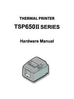
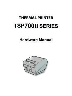
Transcription of Line Thermal Printer STAR Line Mode Command …
1 line Thermal Printer star line Mode Command Specifications Rev star Micronics Co., Ltd. Special Products Division star line Mode Command Specifications 1 Table of Contents 1. INTERFACE CONFIGURATION .. RS-232 Serial Interface .. Specifications (Conforming to RS-232) .. Signal array and explanations according to interface connector pin .. Communication Protocol .. Parallel Interfaces (Amphenol 36 pins) .. Specifications (Conforming to IEEE1284) .. Signal array and explanations according to interface connector pin .. Signal Output Timing .. Status specification .. USB Interface .. Ethernet Interface.
2 Wireless LAN Interface .. Powered USB Interface ..1-62. Command FUNCTION LIST ..2-13. Command DETAILS .. Explanation of Terms .. Exception Processing .. Standard Command Details .. Font style and Character Set ..3-3 .. Character Expansion Settings .. Print Mode .. line Spacing .. Page Control Commands .. Horizontal Direction Printing Position .. Download .. Bit Image Graphics .. Logo .. Bar Code .. Cutter Control .. External Device Drive .. Print Settings .. Status .. Kanji characters .. Others .. Raster Graphics Command Details .. Black Mark Related Command Details .. USB Related Command Details .. 2 Color Printing Command Details .. Presenter Related Command Details.
3 Mark Command Details .. AUTO LOGO Function Command Details .. Two -dimensional Bar Code PDF417 Command Details .. Details of the Print Starting Trigger Control Command .. Two -Dimensional Bar Code QR Code Command Details .. Page Function Command Details .. Reduced Printing Function Command Details .. Page Mode Command Details .. Text Search Command Details .. Audio Command Details .. Graphics data Command Details .. Individual Logo Commands .. Printer Information Transmission Commands ..3-168 star line Mode Command Specifications 2 4. CHARACTER CODE TABLES ..4-15. APPENDIX .. Appendix 1: Bar Code specification Details.
4 Code 39 .. Interleaved 2 of 5 .. JAN/EAN/UPC .. Code 128 .. Code 93 .. NW7 (CODERBAR) .. Appendix 2: Status Specifications .. ENQ Command Status .. EOT Command Status .. Automatic Status .. Printer status transmission specification when using Ethernet I/F and Wireless LAN I/F .. Appendix 3: Blank Code Page Configuration .. Appendix 4 Maximum Number of Input Characters for Each Version of QR Code .. Appendix 5 TSP800L Cut Command Specifications .. Appendix 6 Explanation of Page Mode ..5-235- 6-1. Overview ..5-235-6-2. Setting Values Using Each Command in Standard Mode and Page Mode ..5-235-6-3. Print Data Expansion to the Print Region .. Appendix 7 Explanation of Print Startup Control Starting Printing When Set to Page Units.
5 Appendix 8 Printing NV Bit Images Defined by "GS ( L <fn=67>" or "GS 8 L <fn=67>" with "FS p" .. Appendix 9 Special Specifications when the Bluetooth Interface (IFBD-HB03) is used ..5-286. SPECIAL APPENDIX Command LIST FOR EACH MODEL IN EACH I/F .. RS-232C I/F .. Parallel I/F USB I/F ( ) Powered USB I/F .. USB I/F ( ) Ethernet I/F (Silex ) .. Ethernet I/F .. Wireless LAN I/F .. Bluetooth I/F ..6-31 star line Mode Command Specifications 3 This specifications document describes the Command specifications for the star line MODE on line Thermal printers. Information contained herein applies to models with the following conditions.)
6 - line Thermal printers - Interfaces: - Parallel - RS-232C - USB - Ethernet - Wireless LAN - Powered USB - Bluetooth < Applicable Models:> TSP700 TSP600 TSP800 TUP900 TSP1000 TSP828L TSP700II TSP650 TUP500 TSP800II FVP10 TSP650II star line Mode Command Specifications 1-1 1. INTERFACE CONFIGURATION RS-232 Serial Interface Specifications (Conforming to RS-232) Rating: RS-232C Synch method: Start -Stop synchronization method Handshake: DTR mode Baud rates: 4800, 9600, 19200, 38400 bps (Set by DIP switches) Bit length: 7, 8 bits (Set by DIP switches) Parity: Yes/No (Set by DIP switches) Parity bit: Odd/even (Set by DIP switches) Stop bit: 1 bit (Fixed) Signal polarity: Mark = logic 1 (-3 to -15 V) Space = logic 0 (+3 to +15 V) Signal array and explanations according to interface connector pin <Signal Array and Functions> Pin No.
7 Signal Name Signal Direction Remarks 1 FG - Frame ground 2 TXD OUT Transmission data 3 RXD IN Reception data 4 RTS OUT Same as DTR 5 - Not used 6 DSR IN Not used (Can also be used as an external reset signal by the DIP SW setting. The Printer is reset by mark status over a pulse width of 1 msec.) 7 SG - Signal ground 8-19 - Not used 20 DTR OUT Data terminal ready signal (SPACE: Printer is ready to receive.) 1) When in DTR mode: When Printer is ready to receive data: SPACE 2) When in XON/XOFF mode: Always SPACE except in the following conditions. 1. Until communication is possible after a reset. 2. When test printing 21-24 Signal ground 25 /INIT IN Signal ground (Can also be used as an external reset signal by the DIP SW setting.
8 The Printer is reset by mark status over a pulse width of 1 msec.) star line Mode Command Specifications 1-2 Communication Protocol 1) General description of operations in the DTR mode This mode abides by the DIP switch settings. (Ex-factory settings) This mode performs communication while handshaking with the DTR signals. In the operations to receive Printer data, this mode controls the DTR signals by confirming the BUSY signal. A SPACE indicates that the Printer is ready to recei ve data; conversely, a mark indicates that the Printer cannot receive data. If there is no Printer error after turning ON the power, the DTR signal line is set to a SPACE.
9 When the host computer confirms that the DTR signal line is a SPACE, it sends the data text to the RXD signal line . The Printer sets the DTR signal line to a Mark after the empty area of the data buffer reaches a maximum of 256 bytes. When the host computer confirms that the DTR signal line is a Mark, it stops the transmission of data text to the Printer buffer, but at this point as well, the Printer is still capable of receiving data, up to the amount of empty space in the data buffer. If the host computer ignores the DTR signal and transmits data, all data exceeding the amount of space in the data buffer is simply discarded. The Printer sets the DTR signal line to SPACE again when the amount of empty space in the data buffer increased because of the printing and the data in the buffer is a maximum of 256 bytes.
10 As the empty area in the data buffer increases because of printing, the Printer sets the DTR signal line to SPACE. 2) Buffer full/Buffer full cancel in the DTR mode Full Near Full Near Empty Empty Buffer Empty area: 5 12 bytes Empty area: 256 bytes DTR "Mark" DTR "SPACE" <When ON- line > RXD DATA DATA DATA DTR Printing Power ON Buffer full Buffer empty <When out of paper> RXD OFF- line ON- line DTR ON- line Recovery Printing Out of paper No paper signal Power ON