Transcription of LM185/LM285/LM385 Adjustable Micropower Voltage …
1 lm185 -ADJ, LM285-ADJ, LM385-ADJ. SNVS741F FEBRUARY 2000 REVISED APRIL 2013. LM185/LM285/LM385 Adjustable Micropower Voltage References Check for Samples: lm185 -ADJ, LM285-ADJ, LM385-ADJ. 1 FEATURES Careful design of the lm185 has made the device tolerant of capacitive loading, making it easy to use in . 2 Adjustable from to almost any reference application. The wide dynamic Operating Current of 10 A to 20mA operating range allows its use with widely varying 1% and 2% Initial Tolerance supplies with excellent regulation. 1 Dynamic Impedance The extremely low power drain of the lm185 makes it Low Temperature Coefficient useful for Micropower circuitry. This Voltage reference can be used to make portable meters, regulators or DESCRIPTION general purpose analog circuitry with battery life approaching shelf life. Further, the wide operating The LM185/LM285/LM385 are Micropower 3-terminal current allows it to replace older references with a Adjustable band-gap Voltage reference diodes.
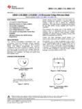
2 Tighter tolerance part. Operating from to and over a 10 A to 20mA current range, they feature exceptionally low The lm185 is rated for operation over a 55 C to dynamic impedance and good temperature stability. 125 C temperature range, while the LM285 is rated On-chip trimming is used to provide tight Voltage 40 C to 85 C and the LM385 0 C to 70 C. The tolerance. Since the lm185 band-gap reference uses lm185 is available in a hermetic TO package and a only transistors and resistors, low noise and good LCCC package, while the LM285/LM385 are long-term stability result. available in a low-cost TO-92 package, as well as SOIC. Connection Diagram Figure 1. TO-92 Package Figure 2. TO Package Bottom View Bottom View Figure 3. SOIC Package Figure 4. 20-LCCC. Top View Top View 1. Please be aware that an important notice concerning availability, standard warranty, and use in critical applications of Texas Instruments semiconductor products and disclaimers thereto appears at the end of this data sheet.
3 2 All trademarks are the property of their respective owners. PRODUCTION DATA information is current as of publication date. Copyright 2000 2013, Texas Instruments Incorporated Products conform to specifications per the terms of the Texas Instruments standard warranty. Production processing does not necessarily include testing of all parameters. lm185 -ADJ, LM285-ADJ, LM385-ADJ. SNVS741F FEBRUARY 2000 REVISED APRIL 2013 Block Diagram Typical Applications Figure 5. reference Figure 6. reference These devices have limited built-in ESD protection. The leads should be shorted together or the device placed in conductive foam during storage or handling to prevent electrostatic damage to the MOS gates. 2 Submit Documentation Feedback Copyright 2000 2013, Texas Instruments Incorporated Product Folder Links: lm185 -ADJ LM285-ADJ LM385-ADJ.
4 lm185 -ADJ, LM285-ADJ, LM385-ADJ. SNVS741F FEBRUARY 2000 REVISED APRIL 2013. Absolute Maximum Ratings (1) (2) (3). Reverse Current 30mA. Forward Current 10mA. (4). Operating Temperature Range lm185 Series 55 C to 125 C. LM285 Series 40 C to 85 C. LM385 Series 0 C to 70 C. (5). ESD Susceptibility 2kV. Storage Temperature 55 C to 150 C. Soldering Information TO-92 Package (10 sec.) 260 C. TO Package (10 sec.) 300 C. SOIC Package Vapor Phase (60 sec.) 215 C. Infrared (15 sec.) 220 C. See An-450 Surface Mounting Methods and Their Effect on Product Reliability for other methods of soldering surface mount devices. (1) Absolute Maximum Ratings indicate limits beyond which damage to the device may occur. Operating Ratings indicate conditions for which the device is intended to be functional. For specifications and test conditions, see the Electrical Characteristics.
5 The specifications apply only for the test conditions listed. (2) Refer to RETS185H for military specifications. (3) If Military/Aerospace specified devices are required, please contact the TI Sales Office/Distributors for availability and specifications. (4) For elevated temperature operation, see Table 1 and Thermal Characteristics. (5) The human body model is a 100 pF capacitor discharged through a k resistor into each pin. Table 1. TJ(max) for Elevated Temperature Operation DEVICE TJ(max) ( C). lm185 150. LM285 125. LM385 100. Thermal Characteristics Over operating free-air temperature range (unless otherwise noted). Thermal Resistance TO-92 TO-46 SOIC. 180 C/W ( leads). JA (Junction to Ambient) 440 C/W 165 C/W. 170 C/W ( leads). JC (Junction to Case) N/A 80 C/W N/A. Copyright 2000 2013, Texas Instruments Incorporated Submit Documentation Feedback 3.
6 Product Folder Links: lm185 -ADJ LM285-ADJ LM385-ADJ. lm185 -ADJ, LM285-ADJ, LM385-ADJ. SNVS741F FEBRUARY 2000 REVISED APRIL 2013 Electrical Characteristics (1). lm185 , LM285 LM385. LM185BX, LM285 LM385. LM185BY. LM385BX, LM185B, LM385BY Units Parameter Conditions LM285BX, Typ Typ (Limit). LM285BY. Tested Design Tested Design Tested Design Tested Design Limit Limit Limit Limit Limit Limit Limit Limit (2) (3) (2) (3) (2) (3) (2) (3). reference IR = 100 A V (max). Voltage V (min). reference IMIN< IR < 1mA 1 1 1 1 mV. Voltage (max). 1mA < IR < 20mA 4 10 20 10 20 5 15 25 15 25. Change with Current Dynamic IR = 100 A, f =. Output 100Hz Impedance IAC = IR VOUT = . VREF. VOUT = 1. reference IR = 100 A. Voltage mV. Change with 1 3 6 3 6 2 5 10 5 10. (max). Output Voltage Feedback 13 20 25 20 25 16 30 35 30 35 nA (max). Current Minimum VOUT = VREF 6 9 10 9 10 7 11 13 11 13 A.
7 Operating (max). VOUT = 30 45 50 45 50 35 55 60 55 60. Current (see curve). Output IR = 100 A, 10Hz < f Vrms Wideband < 10kHz Noise VOUT = VREF 50 50. VOUT = 170 170. Average IR = 100 A X Suffix 30 30. Temperature Y Suffix 50 50 ppm/ c Coefficient (4) (max). All 150 150 150 150. Others Long Term IR = 100 A, T = 1000 20 20 ppm Stability Hr, TA = 25 C C. (1) Parameters identified with boldface type apply at temperature extremes. All other numbers apply at TA = TJ = 25 C. Unless otherwise specified, all parameters apply for VREF < VOUT < (2) Production tested. (3) Not production tested. These limits are not to be used to calculate average outgoing quality levels. (4) The average temperature coefficient is defined as the maximum deviation of reference Voltage at all measured temperatures from TMIN. to TMAX, divided by TMAX TMIN.
8 The measured temperatures are 55, 40, 0, 25, 70, 85, 125 C. 4 Submit Documentation Feedback Copyright 2000 2013, Texas Instruments Incorporated Product Folder Links: lm185 -ADJ LM285-ADJ LM385-ADJ. lm185 -ADJ, LM285-ADJ, LM385-ADJ. SNVS741F FEBRUARY 2000 REVISED APRIL 2013. Typical Performance Characteristics Temperature Drift of 3. Representative Units Feedback Current Figure 7. Figure 8. Minimum Operating Current Reverse Characteristics Figure 9. Figure 10. Reverse Characteristics Forward Characteristics Figure 11. Figure 12. Copyright 2000 2013, Texas Instruments Incorporated Submit Documentation Feedback 5. Product Folder Links: lm185 -ADJ LM285-ADJ LM385-ADJ. lm185 -ADJ, LM285-ADJ, LM385-ADJ. SNVS741F FEBRUARY 2000 REVISED APRIL 2013 Typical Performance Characteristics (continued). Output Noise Voltage Dynamic Output Impedance Figure 13.
9 Figure 14. Response Time Figure 15. Temperature Coefficient Typical lm185 (left), LM285 (center), LM385 (right). Figure 16. 6 Submit Documentation Feedback Copyright 2000 2013, Texas Instruments Incorporated Product Folder Links: lm185 -ADJ LM285-ADJ LM385-ADJ. lm185 -ADJ, LM285-ADJ, LM385-ADJ. SNVS741F FEBRUARY 2000 REVISED APRIL 2013. TYPICAL APPLICATIONS. Figure 17. Precision 10V reference Figure 18. Low AC Noise reference Figure 19. 25V Low Current Shunt Regulator Figure 20. 200 mA Shunt Regulator Copyright 2000 2013, Texas Instruments Incorporated Submit Documentation Feedback 7. Product Folder Links: lm185 -ADJ LM285-ADJ LM385-ADJ. lm185 -ADJ, LM285-ADJ, LM385-ADJ. SNVS741F FEBRUARY 2000 REVISED APRIL 2013 Figure 21. Series-Shunt 20 mA Regulator Figure 22. High Efficiency Low Power Regulator Figure 23. Voltage Level Detector Figure 24.
10 Voltage Level Detector Figure 25. Fast Positive Clamp Figure 26. Bidirectional Clamp + VD1 8 Submit Documentation Feedback Copyright 2000 2013, Texas Instruments Incorporated Product Folder Links: lm185 -ADJ LM285-ADJ LM385-ADJ. lm185 -ADJ, LM285-ADJ, LM385-ADJ. SNVS741F FEBRUARY 2000 REVISED APRIL 2013. Figure 27. Bidirectional Adjustable Clamp Figure 28. Bidirectional Adjustable Clamp to to 6V. Figure 29. Simple Floating Current Detector Figure 30. Current Source Copyright 2000 2013, Texas Instruments Incorporated Submit Documentation Feedback 9. Product Folder Links: lm185 -ADJ LM285-ADJ LM385-ADJ. lm185 -ADJ, LM285-ADJ, LM385-ADJ. SNVS741F FEBRUARY 2000 REVISED APRIL 2013 *D1 can be any LED, VF= to at 3 mA. D1 may act as an indicator. D1 will be on if ITHRESHOLD falls below the threshold current, except with I=O. Figure 31.