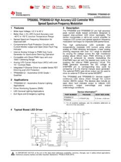
Transcription of LMR14050-Q1 SIMPLE SWITCHER® 40 V, 5 A Step …
1 IOUT (A)Efficiency (%) = 12 V, gSW = 300 kHzVOUT = 5 VVOUT = VBOOTSWLCBOOTFBVINVIN up to 40 VGNDCOUTENCINSSRT/SYNCVOUT CSSDRFBTRFBBRTP roductFolderSample &BuyTechnicalDocumentsTools &SoftwareSupport &CommunityAn IMPORTANTNOTICEat the end of this datasheetaddressesavailability,warranty, changes,use in safety-criticalapplications,intellectual propertymattersand NOVEMBER2015 REVISEDJULY2016 LMR14050-Q1 SIMPLESWITCHER 40 V, 5 A Step-DownConverterwith 40 A IQ11 Features1 Qualifiedfor AutomotiveApplications AEC-Q100 QualifiedWiththe FollowingResults:- DeviceTemperatureGrade1: -40 C to 125 CAmbientOperatingTemperatureRange- DeviceHBMESDC lassificationLevelH1C- DeviceCDMESDC lassificationLevelC4A 4 V to 40 V InputRange 5 A ContinuousOutputCurrent Ultra-low40 A OperatingQuiescentCurrent 90 m High-SideMOSFET MinimumSwitch-OnTime.
2 75 ns CurrentModeControl AdjustableSwitchingFrequencyfrom200 kHz MHz FrequencySynchronizationto ExternalClock SpreadSpectrumOptionfor ReducedEMI InternalCompensationfor Easeof Use HighDutyCycleOperationSupported PrecisionEnableInput 1 A ShutdownCurrent ExternalSoft-start Thermal,Overvoltageand ShortProtection 8-PinHSOIC with PowerPAD Package2 Applications AutomotiveBatteryRegulation IndustrialPowerSupplies Telecomand DatacomSystems GeneralPurposeWideVin Regulationspace3 DescriptionTheLMR14050-Q1is a 40 V, 5 A stepdownregulatorwith an wideinputrangefrom4 V to 40 V, it s suitableforvariousapplicationsfromindust rialto availablein 2 A and A optionsin pin-to-pincompatiblepackages, squiescentcurrentis 40 A in Sleep-mode,whichissuitablefor ultra-low1 A currentin shutdownmodecan furtherprolongbatterylife.
3 A wideadjustableswitchingfrequencyrangeall owseitherefficiencyor externalcomponentsizeto be the useris free fromthe the precisionenableinputallowssimplification of regulatorcontroland devicealsohasbuilt-inprotectionfeaturess uchas cycle-by-cyclecurrentlimit,thermalsensin gand shutdowndue toexcessivepowerdissipation,and LMR14050-Q1is availablein an 8-pinHSOICor10-pinWSON packagewithexposedpadfor (1)PARTNUMBERPACKAGEBODYSIZE(NOM)LMR1405 0 SQDDARQ1 HSOIC(8) x (SpreadSpectrum)HSOIC(8) x (10) x (SpreadSpectrum)WSON(10) x (1) For all availablepackages,see the orderableaddendumatthe end of the OutputCurrent2 LMR14050-Q1 SNVSAG2A NOVEMBER2015 : LMR14050-Q1 SubmitDocumentationFeedbackCopyright 2015 2016,TexasInstrumentsIncorporatedTableof Contents1 Pin Configurationand Applicationand Deviceand Mechanical,Packaging,and RevisionHistoryNOTE:Pagenumbersfor previousrevisionsmay differfrompagenumbersin the (November2015)to RevisionAPage Addednew columnfor Addednew sectionfor Pad(11)FBSSGNDSWBOOTVINENRT/SYNCT hermal Pad(9) NOVEMBER2015 REVISEDJULY2016 ProductFolderLinks.
4 LMR14050-Q1 SubmitDocumentationFeedbackCopyright 2015 2016,TexasInstrumentsIncorporated(1)A = Analog,P = Power,G = Ground5 Pin Configurationand FunctionsDDAP ackage8-Pin(HSOIC)Top ViewDPRP ackage10-Pin(WSON)Top ViewPin (1)DESCRIPTIONSO-8 WSON-10 BOOT11 PBootstrapcapacitorconnectionfor F capacitorfromBOOTto , 3 PConnectto powersupplyand bypasscapacitorsCIN. PathfromVIN pin to highfrequencybypassCINand GNDmustbe as shortas , with V to connectto VIN to inputundervoltagelockoutwith the Enableand internalamplifierholdsthis pin at afixedvoltagewhenusingan externalresistorto groundto set the the pin is pulledabovethe PLL upperthreshold,a modechangeoccursand the pin becomesa internalamplifierisdisabledand the pin is a high impedanceclockinputto the clockingedgesstop,the internalamplifieris re-enabledand the operatingmodereturnstofrequencyprogrammi ngby , connectto the feedbackdividerto set VOUT.
5 Do not shortthispin to Connectto a capacitorto set power-goodflag. Use a 10 k to 100 k pull-upresistortologicrail or otherDC voltageno the the die. Mustbe connectedto groundplaneon NOVEMBER2015 : LMR14050-Q1 SubmitDocumentationFeedbackCopyright 2015 2016,TexasInstrumentsIncorporated(1)Stre ssesbeyondthoselistedunderAbsoluteMaximu mRatingsmay causepermanentdamageto the stressratingsonly,whichdo not implyfunctionaloperationof the deviceat theseor any otherconditionsbeyondthoseindicatedunder RecommendedOperatingConditions. Exposureto absolute-maximum-ratedconditionsfor extendedperiodsmay recommendedoperatingjunctiontemperaturer angeof -40 C to 125 C (unlessotherwisenoted)(1)MINMAXUNITI nputVoltagesVIN,EN to to to to GND-344 TJJunctiontemperature-40150 CTstgStoragetemperature-65150 C(1)AECQ100-002indicatesthat HBMstressingshallbe in accordancewith the ANSI/ (ESD)ElectrostaticdischargeHuman-bodymod el(HBM),per AECQ100-002(1) 2000 VCharged-devicemodel(CDM),per AECQ100-011 750(1)OperatingRatingsindicateconditions for whichthe deviceis intendedto be functional,but do not guaranteedspecifications, recommendedoperatingjunctiontemperaturer angeof -40 C to 125 C (unlessotherwisenoted)(1)
6 GND05 FrequencySwitchingfrequencyrangeat RT mode2002500kHzSwitchingfrequencyrangeat SYNC mode2502300 TemperatureOperatingjunctiontemperature, TJ-40125 NOVEMBER2015 REVISEDJULY2016 ProductFolderLinks: LMR14050-Q1 SubmitDocumentationFeedbackCopyright 2015 2016,TexasInstrumentsIncorporated(1)For moreinformationabouttraditionaland new thermalmetrics,see theSemiconductorand IC PackageThermalMetricsapplicationreport,S PRA953.(2)Powerratingat a specificambienttemperatureTAshouldbe determinedwith a maximumjunctiontemperature(TJ) of 125 C, (1) (2) LMR14050-Q1 UNITDDA(HSOIC)DPR(WSON)8 PINS10 PINSR C/W C/W C/WR JC(top)Junction-to-case(top) C/WR JC(bot)Junction-to-case(bottom) C/WR recommendedoperatingjunctiontemperature( TJ) rangeof -40 C to +125 C, Maximumlimitsare specifiedthroughtest, designor mostlikelyparametricnormat TJ= 25 C, and are providedfor ,the followingconditionsapply.
7 VIN= V to 40 VPARAMETERTESTCONDITIONSMINTYPMAXUNITPOW ERSUPPLY(VINPIN) 0 V, TJ= 25 C, V VIN 40 AIQO peratingquiescentcurrent(non-switching)V FB= V, TJ= 25 C40 AENABLE(EN PIN)VEN_THEN PIN currentEnablethreshold+50 AEnablethreshold-50 AEXTERNALSOFT-STARTISSSS pin currentTJ= 25 C-3 APOWERGOOD(PGOODPIN)VPG_UVPower-goodflag undervoltagetrippingthresholdPOWERGOOD(% of FB voltage)94%POWERBAD(% of FB voltage)92%VPG_OVPower-goodflag overvoltagetrippingthresholdPOWERBAD(% of FB voltage)109%POWERGOOD(% of FB voltage)107%VPG_HYSP ower-goodflag recoveryhysteresis% of FB voltage2%IPGPGOOD leakagecurrentat high leveloutputVPull-Up= 5 V10200nAVPG_LOWPGOODlow leveloutputvoltageIPull-Up= 1 for validPGOOD outputVPull-Up< 5 V at IPull-Up= 100 (FB PIN)VFBF eedbackvoltageTJ= 25 -40 C to 125 12 V, BOOTto SW = V90180m 6 LMR14050-Q1 SNVSAG2A NOVEMBER2015 : LMR14050-Q1 SubmitDocumentationFeedbackCopyright 2015 2016,TexasInstrumentsIncorporatedElectri calCharacteristics(continued)Limitsapply overthe recommendedoperatingjunctiontemperature( TJ) rangeof -40 C to +125 C, Maximumlimitsare specifiedthroughtest, designor mostlikelyparametricnormat TJ= 25 C, and are providedfor ,the followingconditionsapply.
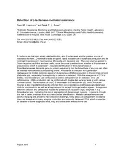
8 VIN= V to 40 VPARAMETERTESTCONDITIONSMINTYPMAXUNITHIG H-SIDEMOSFETCURRENTLIMITILIMTC urrentlimitVIN= 12 V, TJ= -40 C to 125 C, recommendedoperatingjunctiontemperaturer angeof -40 C to 125 C (unlessotherwisenoted)PARAMETERTESTCONDI TIONSMINTYPMAXUNITfSWSwitchingfrequencyR T= 175819122066kHzSwitchingfrequencyrangeat SYNC mode2502300 FDITHERS witchingfrequencyditheringSpreadspectrum option,frequencyditheringovercenterfrequ ency 6%VSYNC_HISYNC clockhigh 500 kHz,VSYNC_HI> 3 V,VSYNC_LO< V30nsTLOCK_INPLL lock in timeMeasuredat 500 kHz100 sTON_MINM inimumcontrollableon timeVIN= 12 V, BOOTto SW = V, ILoad=1 A75nsDMAXM aximumduty cyclefSW= 200 kHz97%IOUT (A)VOUT Deviation (%) = 36 VVIN = 24 VVIN = 12 VVFB (V)Nominal Switching Frequency (%) FallingVFB RisingIOUT (A)Efficiency (%) = 24 VVIN = 12 VVIN = 5 VIOUT (A)Efficiency (%) = 24 VVIN = 12 VVIN = 5 VIOUT (A)Efficiency (%) = 36 VVIN = 24 VVIN = 12 VIOUT (A)Efficiency (%) = 36 VVIN = 24 VVIN = 12 NOVEMBER2015 REVISEDJULY2016 ProductFolderLinks: LMR14050-Q1 SubmitDocumentationFeedbackCopyright 2015 2016, followingconditionsapply:VIN= 12 V, fSW= 300 kHz,L = H, COUT= 47 F x 4, TA= 25 CVOUT= 5 VfSW= 300 kHzFigure1.
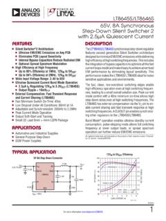
9 Efficiencyvs. LoadCurrentVOUT= 5 VfSW= 500 kHzFigure2. Efficiencyvs. LoadCurrentVOUT= VfSW= 300 kHzFigure3. Efficiencyvs. LoadCurrentVOUT= VfSW= 500 kHzFigure4. Efficiencyvs. LoadCurrentVOUT= 5 VfSW= 300 kHzFigure5. LoadRegulationFigure6. Frequencyvs VFBVIN (V)IQ & ISHDN ( A)051015202530354045051015202530354045 IQISHDND006 Temperature ( C)UVLO (V) (V)VOUT (V) = 5 AIOUT = AIOUT = AVIN (V)VOUT (V) = 5 AIOUT = AIOUT = AVIN (V)VOUT (V) = 5 AIOUT = AIOUT = AVIN (V)VOUT (V) = 5 AIOUT = AIOUT = A8 LMR14050-Q1 SNVSAG2A NOVEMBER2015 : LMR14050-Q1 SubmitDocumentationFeedbackCopyright 2015 2016,TexasInstrumentsIncorporatedTypical Characteristics(continued)Unlessotherwis especifiedthe followingconditionsapply:VIN= 12 V, fSW= 300 kHz,L = H, COUT= 47 F x 4, TA= 25 CVOUT= 5 VfSW= 300 kHzFigure7.
10 DropoutCurveVOUT= 5 VfSW= 500 KHzFigure8. DropoutCurveVOUT= VfSW= 300 kHzFigure9. DropoutCurveVOUT= VfSW= 500 kHzFigure10. DropoutCurveFigure11. Shut-downCurrentand QuiescentCurrentIOUT= 0 AFigure12. UVLOT hresholdERROR AMPLIFIERBoot ChargeBoot UVLOO scillator with PLLF requencyShiftPWM ControlLogicSlope CompensationPWMC omparatorVoltageReferenceFBVINGNDT hermal ShutdownENEnableComparatorShutdownLogicS hutdownEnableThreshold6 ShutdownOVCompComponentsBootstrap NOVEMBER2015 REVISEDJULY2016 ProductFolderLinks: LMR14050-Q1 SubmitDocumentationFeedbackCopyright 2015 2016,TexasInstrumentsIncorporated7 LMR14050-Q1 SIMPLESWITCHER regulatoris an easyto use step-downDC-DCconverterthat operatesfroma V to 40 V integratesa 90 m (typical)high-sideMOSFET,and is capableofdeliveringup to 5 A DC load currentwith exceptionalefficiencyand thermalperformancein a very typically40 A underno loadcondition(notswitching).