Transcription of Load-sharing techniques: Paralleling power modules with ...
1 5 Analog Applications JournalLoad- sharing techniques: Paralleling powermodules with overcurrent protectionParalleling low-current, low-voltage power modules forhigh-current, low-voltage applications has many them are: redundancy for enhanced reliability, hot-swap capability, distributed heat removal, and design flexi-bility. Paralleling power stages requires load sharing inorder to equalize the stresses among the modules . Onemethod of load sharing , based upon the automatic master/slave architecture, is to use a dedicated controller, such asthe UCC39002, to provide for equal current distribution ofthe load current among the parallel-connected power sup-plies.
2 The power modules must be equipped with trueremote-sense capability or an output-adjustment output current of each module is measured and com-pared to a common load -share bus. The positive sensevoltage or the voltage of the output voltage adjust pin ofeach module is adjusted to provide equal current modules are paralleled so that the entire assem-bly can support a full load much greater than an individualmodule would be capable of supplying. Due to manufactur-ing tolerances and component variations, startup delaytimes typically vary slightly from module to module . Whenthe modules to be paralleled have an overcurrent protectioncircuit featuring constant current limit with automaticrecovery, starting up fully enabled into the full system loaddoes not pose a problem.
3 Inevitably, one module will haveTexas Instruments IncorporatedPower ManagementBy Lisa Dinwoodie (Email: Applications Specialist1Q and Mixed-Signal Productsa faster turn-on than the others. The eager module willcarry as much of the load as it can, sometimes up to 140%of its individual current capacity, before its output voltagefalters. Meanwhile, the next module will come up and con-tribute to the load . After a brief transition time, all of themodules will be up, the master will be recognized, andaccurate load sharing will take the modules to be paralleled have an overcurrentprotection circuit featuring a hiccup mode, starting up fullyenabled into full system load , regardless of the load sharingtechnique used, does pose a problem.)
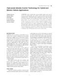
4 The module withthe fastest turn-on profile will come up into an overcurrentcondition. Immediately, in an act of self-preservation, itwill go into hiccup mode, alternately sinking and sourcingcurrent. The next module to come up into the load willalso fall into this hiccup mode, sinking current when theother module sources it. Because the load -share circuitryessentially adds a voltage loop to the output of each mod-ule, this hiccupping overcurrent protection mode will prevent loop closure. Simultaneously enabling the moduleswill prevent this hiccup mode from starting, and load shar-ing can be successfully 1 shows a simple comparator circuit that willsimultaneously enable two modules and can be expandedto accommodate more if needed.
5 It assumes that the onlyIN+ fromModule 1IN+ fromModule 2E2 module 2ON/OFFE1 module 1 FC21 FU2:BLM393U2:ALM393Q22N2907 ASN74 AHC1G00C11 k D115 VD215 VD215 k k k R7143 k R4357 k R8357 k M M 26354811254U3 GND3 VCC7R9143 k R1210 k R1310 k k k k Q12N2907J1J2 Figure 1. Logic circuit to turn on two power modules simultaneouslyTexas Instruments IncorporatedPower Management6 Analog Applications JournalAnalog and Mixed-Signal 2003bias available for the logic gates is the 48-Vdc bus used asthe input to the modules themselves. The circuit is designedto short the modules on/off pins to ground simultaneouslywhen their inputs reach 35 V, assuming that the modules input range is between 36 V and 75 V and that they have aturn-on threshold of approximately 33 PNP transistor, Q1, its emitter and base resistors,and the two 15-V Zener diodes provide a 15-V, 5-mA biasto the comparators and the NAND gate from the inputline, which could vary from 36 Vdc to 75 Vdc.
6 The TL431is set up to provide a regulated 10-V reference voltage forthe inverted comparator inputs. The non-inverted com-parator input signals are derived from resistively dividingthe input voltages of the modules . Because the bias andcomparator signals are from the same source, capacitorsare needed to delay the comparator input signals longenough so that the LM393, U2, is operational and smart. This circuit is added to the load -share board and success-fully turns on the modules simultaneously into a full systemload without triggering the overcurrent hiccup mode ofthe Web partnumberwith LM393, SN74 AHC1G00, TL431or UCC39002 IMPORTANT NOTICE Texas Instruments Incorporated and its subsidiaries (TI)
7 Reservethe right to make corrections, modifications, enhancements,improvements, and other changes to its products and services atany time and to discontinue any product or service without should obtain the latest relevant information beforeplacing orders and should verify that such information is currentand complete. All products are sold subject to TI's terms andconditions of sale supplied at the time of order acknowledgment. TI warrants performance of its hardware products to thespecifications applicable at the time of sale in accordance with TI'sstandard warranty. Testing and other quality control techniques areused to the extent TI deems necessary to support this where mandated by government requirements, testing ofall parameters of each product is not necessarily performed.
8 TI assumes no liability for applications assistance or customerproduct design. Customers are responsible for their products andapplications using TI components. To minimize the risksassociated with customer products and applications, customersshould provide adequate design and operating safeguards. TI does not warrant or represent that any license, either express orimplied, is granted under any TI patent right, copyright, mask workright, or other TI intellectual property right relating to anycombination, machine, or process in which TI products or servicesare used. Information published by TI regarding third-partyproducts or services does not constitute a license from TI to usesuch products or services or a warranty or endorsement of such information may require a license from a third partyunder the patents or other intellectual property of the third party, or alicense from TI under the patents or other intellectual property of of information in TI data books or data sheets ispermissible only if reproduction is without alteration and isaccompanied by all associated warranties, conditions, limitations,and notices.
9 Reproduction of this information with alteration is anunfair and deceptive business practice. TI is not responsible orliable for such altered documentation. Resale of TI products or services with statements different from orbeyond the parameters stated by TI for that product or servicevoids all express and any implied warranties for the associated TIproduct or service and is an unfair and deceptive businesspractice. TI is not responsible or liable for any such statements. Following are URLs where you can obtain information on otherTexas Instruments products and application solutions.
10 TI Worldwide Technical SupportInternetTI Semiconductor Product Information Center Home Semiconductor KnowledgeBase Home Information CentersAmericasPhone+1(972) 644-5580 Fax+1(972) 927-6377 , Middle East, and AfricaPhoneBelgium (English) +32 (0) 27 45 54 32 Netherlands (English) +31 (0) 546 87 95 45 Finland (English)+358 (0) 9 25173948 Russia+7 (0) 95 7850415 France+33 (0) 1 30 70 11 64 Spain+34 902 35 40 28 Germany+49 (0) 8161 80 33 11 Sweden (English)+46 (0) 8587 555 22 Israel (English)1800 949 0107 United Kingdom+44 (0) 1604 66 33 99 Italy800 79 11 37 Fax+(49) (0) 8161 80 +81-3-3344-5317 Domestic0120-81-0036 +886-2-23786800 DomesticToll-Free NumberToll-Free NumberAustralia1-800-999-084 New Zealand0800-446-934 China800-820-8682 Philippines1-800-765-7404 Hong Harbor Statement:This publication may contain forward-looking statements that involve a number of risks anduncertainties.