Transcription of LOCAL BUCKLING AND SECTION CLASSIFICATION
1 LOCAL BUCKLING AND SECTION CLASSIFICATION 8 LOCAL BUCKLING AND SECTION CLASSIFICATION INTRODUCTION Sections normally used in steel structures are I-sections, Channels or angles etc. which are called open sections, or rectangular or circular tubes which are called closed sections. These sections can be regarded as a combination of individual plate elements connected together to form the required shape. The strength of compression members made of such sections depends on their slenderness ratio. Higher strengths can be obtained by reducing the slenderness ratio by increasing the moment of inertia of the cross- SECTION . Similarly, the strengths of beams can be increased, by increasing the moment of inertia of the cross- SECTION .
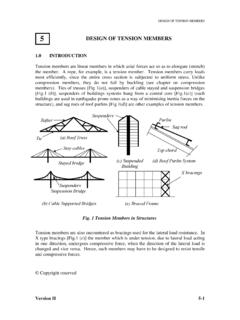
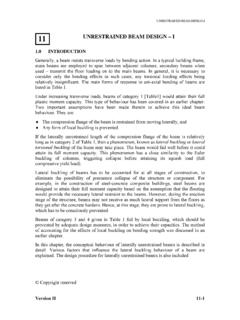
2 For a given cross-sectional area, higher moment of inertia can be obtained by making the sections thin-walled. As discussed earlier, plate elements laterally supported along edges and subjected to membrane compression or shear may buckle prematurely. Therefore, the BUCKLING of the plate elements of the cross SECTION under compression /shear may take place before the overall column BUCKLING or overall beam failure by lateral BUCKLING or yielding. This phenomenon is called LOCAL BUCKLING . Thus, LOCAL BUCKLING imposes a limit to the extent to which sections can be made thin-walled. Consider an I- SECTION column, subjected to uniform compression [Fig. 1(a)]. It was pointed out in the chapter on Introduction to Plate BUCKLING that plates supported on three sides (outstands) have a BUCKLING coefficient k roughly one-tenth that for plates supported on all four sides (internal elements).
3 Therefore, in open sections such as I-sections, the flanges which are outstands tend to buckle before the webs which are supported along all edges. Further, the entire length of the flanges is likely to buckle in the case of the axially compressed member under consideration, in the form of waves. On the other hand, in closed sections such as the hollow rectangular SECTION , both flanges and webs behave as internal elements and the LOCAL BUCKLING of the flanges and webs depends on their respective width-thickness ratios. In this case also, LOCAL BUCKLING occurs along the entire length of the member and the member develops a chequer board wave pattern [Fig. 1(b)]. In the case of beams, the compression flange behaves as a plate element subjected to uniform compression and, depending on whether it is an outstand or an internal element, undergoes LOCAL BUCKLING at the corresponding critical BUCKLING stress.
4 However, the web is partially under compression and partially under tension. Even the part in compression is not under uniform compression . Therefore the web buckles as a plate subjected to in-plane bending compression . Normally, the bending moment varies over the length of the beam and so LOCAL BUCKLING may occur only in the region of maximum bending moment. Copyright reserved Version II 8-1 LOCAL BUCKLING AND SECTION CLASSIFICATION (a) (b)Fig. 1 LOCAL BUCKLING of compression members LOCAL BUCKLING has the effect of reducing the load carrying capacity of columns and beams due to the reduction in stiffness and strength of the locally buckled plate elements. Therefore it is desirable to avoid LOCAL BUCKLING before yielding of the member.
5 Most of the hot rolled steel sections have enough wall thickness to eliminate LOCAL BUCKLING before yielding. However, fabricated sections and thin-walled cold-formed steel members usually experience LOCAL BUCKLING of plate elements before the yield stress is reached. It is useful to classify sections based on their tendency to buckle locally before overall failure of the member takes place. For those cross-sections liable to buckle locally, special precautions need to be taken in design. However, it should be remembered that LOCAL BUCKLING does not always spell disaster. LOCAL BUCKLING involves distortion of the cross- SECTION . There is no shift in the position of the cross- SECTION as a whole as in global or overall BUCKLING . In some cases, LOCAL BUCKLING of one of the elements of the cross- SECTION may be allowed since it does not adversely affect the performance of the member as a whole.
6 In the context of plate bucking, it was pointed out that substantial reserve strength exists in plates beyond the point of elastic BUCKLING . Utilization of this reserve capacity may also be the objective of design. Therefore, LOCAL BUCKLING may be allowed in some cases, provided due care is taken to estimate the reduction in the capacity of the SECTION due to it and the consequences are clearly understood. In what follows, first the basic concepts of plastic theory are introduced. Then the CLASSIFICATION of cross-sections is described. The codal provisions limiting the width-thickness ratios of plate elements in a cross- SECTION are given. Finally the implications in design are discussed. BASIC CONCEPTS OF PLASTIC THEORY Before attempting the CLASSIFICATION of sections, the basic concepts of plastic theory will be introduced.
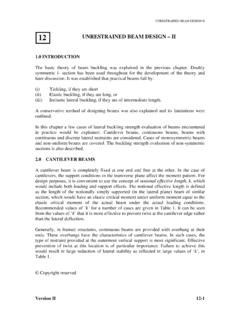
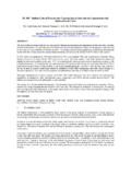
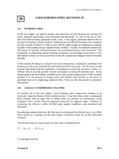
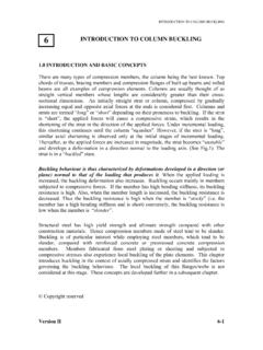
7 More detailed descriptions can be found in subsequent chapters. Version II 8-2 LOCAL BUCKLING AND SECTION CLASSIFICATION Bending Moment DiagramPlastic hinges MpCollapse mechanism Plastic hinges Mpw Mp Fig. 2 Formation of a Collapse Mechanism in a Fixed Beam Consider a beam with both ends fixed and subjected to a uniformly distributed load of w per meter length as shown in Fig. 2(a). The elastic bending moment at the ends is w 2/12 and at mid-span is w 2/24, where is the span. The stress distribution across any cross SECTION is linear [Fig. 3(a)]. As w is increased gradually, the bending moment at every SECTION increases and the stresses also increase. At a SECTION close to the support where the bending moment is maximum, the stresses in the extreme fibers reach the yield stress.
8 The moment corresponding to this state is called the first yield moment My, of the cross SECTION . But this does not imply failure as the beam can continue to take additional load. As the load continues to increase, more and more fibers reach the yield stress and the stress distribution is as shown in Fig 3(b). Eventually the whole of the cross SECTION reaches the yield stress and the corresponding stress distribution is as shown in Fig. 3(c). The moment corresponding to this state is known as the plastic moment of the cross SECTION and is denoted by Mp. The ratio of the plastic moment to the yield moment is known as the shape factor since it depends on the shape of the cross SECTION . The cross SECTION is not capable of resisting any additional moment but may maintain this moment for some amount of rotation in which case it acts like a plastic hinge.
9 If this is so, then for further loading, the beam, acts as if it is simply supported with two additional moments Mp on either side, and continues to carry additional loads until a third plastic hinge forms at mid-span when the bending moment at that SECTION reaches Mp. The beam is then said to have developed a collapse mechanism and will collapse as shown in Fig 2(b). If the SECTION is thin-walled, due to LOCAL BUCKLING , it may not be able to sustain the moment for additional rotations and may collapse either before or soon after attaining the plastic moment. It may be noted that formation of a single plastic hinge gives a collapse mechanism for a simply supported beam. The ratio of the ultimate rotation to the yield rotation is called the rotation capacity of the SECTION .
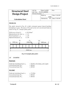
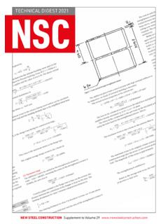
10 The yield and the plastic moments together with the rotation capacity of the cross- SECTION are used to classify the sections. SECTION CLASSIFICATION Sections are classified depending on their moment-rotation characteristics (Fig. 4). The codes also specify the limiting width-thickness ratios = b/t for component plates, which enables the CLASSIFICATION to be made. Version II 8-3 LOCAL BUCKLING AND SECTION CLASSIFICATION (a) at My (b) My < M<Mp(c) at Mp Fig. 3 Plastification of Cross- SECTION under Bending Plastic cross-sections: Plastic cross-sections are those which can develop their full-plastic moment Mp and allow sufficient rotation at or above this moment so that redistribution of bending moments can take place in the structure until complete failure mechanism is formed (b/t 1) (see Fig.)