Transcription of Low Voltage Products Low Voltage Capacitors Power Factor ...
1 Low Voltage Products Low Voltage Capacitors Power Factor Correction Solutions Low Voltage Capacitors Reliability for Power Factor Correction Dry type design Unique protection system The ABB Low Voltage Capacitors , called CLMD, use dry type A unique Sequential Protection System ensures that each dielectric and therefore avoid any risk of leakage or pollution in individual element can be disconnected from the circuit at the the environment. end of its life. Very low losses Easy to install - light weight Dielectric losses are less than Watt per kvar. Total losses, The CLMD capacitor light weight makes it easy to handle and including discharge resistors, are less than Watt per kvar. install. Long life - Self-healing High reliability In the event of a fault developing in the capacitor's dielectric, The use of robust terminals removes the risk of damage during the metalized electrode adjacent to the fault is immediately va- installation and reduces maintenance requirements.
2 Porized, thus insulating the fault. The capacitor then continues normal operation. Security Thermal equalizers are fitted to surround each capacitor Fire protection element and provide effective heat dissipation. The CLMD. All elements within the CLMD capacitor are surrounded by capacitor is equipped with discharge resistors. vermiculite which is an inorganic, inert, fire proof and non toxic granular material. In the event of any failure the vermiculite ISO 9001. absorbs safely the energy produced within the capacitor box Our ISO 9001 Quality System registration provides the strongest and extinguishes any possible flames. assurance of our product quality. ISO 14001. The CLMD capacitor has a dry type dielectric and is free from liquids or other impregnating agents. It has been designed for environmentally friendly manufacturing. Our ISO 14001. certification guarantees our commitment to the environment.
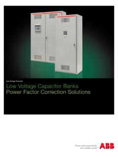
3 Figure 1: LV Capacitors series 2 Reliability for Power Factor Correction | Low Voltage Capacitors Low Voltage Capacitors Construction Principal components of a 3-phase capacitor 3. Terminal studs Principal components of a 3-phase ABB capacitor include: Large terminal studs are located inside the enclosure at the 1. Sequential protection system: top of the capacitor for quick and easy cable connections. Self-healing capacitor elements One or more self-healing capacitor elements are installed 4. Enclosure for each phase. In case of dielectric breakdown, the fault is All ABB enclosures are made of welded heavy gauge steel. cleared by evaporation of the metalized layer around the Available enclosure types include Indoor NEMA 1, Outdoor breakdown with negligible loss of capacitance and Rain tight NEMA 3R, and Indoor Dust tight NEMA 12. continued operation of the capacitor! Internally protected elements What is the significance of dry type design?
4 A unique Sequential Protection System including the IPE ABB low Voltage Capacitors contain no free liquids and are design (IPE - internally protected elements) ensures that filled with a unique non-flammable granular material called each individual element can be disconnected from the vermiculite. Environmental and personnel concerns associated circuit at the end of the element's life. with leakage or flammability of conventional oil-filled units are Non-flammable dry vermiculite filler eliminated; and kvar for kvar, vermiculite filled units weigh 30%. Vermiculite is a dry, granular insulating material that is solid, to 60% less than their oil filled counterparts. inert and fire proof. This material fills all open spaces in the enclosure to isolate the capacitor elements and exclude Vermiculite is used as an insulating material in the walls and free oxygen. ceilings of new buildings. Its properties have been extensively documented and recognized as an ideal material for safety and 2.
5 Discharge resistors environmental considerations. Discharge resistors (one for each phase) are sized to ensure safe discharge of the capacitor to less than 50 volts in one minute or less as required by the National Electrical Code (NEC). Figure 2: IPE construction Figure 3: Low Voltage capacitor construction Low Voltage Capacitors | Construction 3. Low Voltage Capacitors Construction What is a metalized-film element? The IPE sequential protection system Metalized-film is a microscopically thin layer of conducting ABB's metalized-film self-healing capacitor elements will have a material (called an electrode), usually aluminium or zinc on longer life than their conventional foil design counterparts for the an underlying layer of insulating film. The electrode thickness above reason. However, accumulated effects of time, tempera- averages only .01 microns while insulating (polypropylene) film ture, Voltage stress, etc.
6 , eventually effect capacitor life. ranges from 5 to 10 microns in thickness depending upon the design Voltage of the capacitor (the higher the Voltage rating, ABB s sequential protection system featuring patented Internally the thicker the insulating film). Protected Elements (IPE) design provides increased protection to facilities and personnel not available from other capacitor designs. This proven design allows for self-healing throughout the life of the capacitor to insure the maximum length of reliable service and still provide short circuit protection in each element when self-healing can no longer continue. This is accomplished by a combination of unique winding construction and an internal fuse link (See Fig. 6) within each element which safely and selec- tively disconnects each individual element. ABB Capacitors do not rely on mechanical pressure interrupters and additional line fuses have disadvantages associated with that kind of construction.
7 Figure 4: Metalized-film element More about self-healing elements Self-healing is a characteristic which is unique to metalized electrode Capacitors . All capacitor normally experience insulation breakdown as a result of the accumulated effect of tempera- ture, Voltage stress, impurities in the insulating medium, etc. When this happens in a non- metalized design, the electrodes are short-circuited and the capacitor ceases its production of reactive Power . In an ABB metalized-film unit, however, these individual insulation breakdowns do not mean the shutdown of Figure 6: IPE sequential protection system the capacitor. The faults self-heal themselves and the capacitor continues operation. The conducting electrode is very thin; when Advantages of metalized-film elements a short circuit develops as a result of a fault in the insulating There are two electrode layers separated by one layer of dielectric, the thin electrode vaporizes around the area of the insulating film.
8 Thousands of these layers are tightly wound fault. This vaporization continues until sufficient separation exists around a core in such a manner that the edge of one electrode between the faulted electrodes to overcome the Voltage level. is exposed on one side of the element and the edge of the other electrode is exposed on the other side of the element. Wires are then connected to each side of the element. The element is enclosed in a container and then filled with a hardening protective sealant. 1. Self-healing design A B. Self-healing refers to a process where a short circuit between Figure 5: Self-healing element electrodes vaporizes the electrode around the fault (see Fig. 5a). The entire process of self-healing takes microseconds and the until the fault is eliminated. The element continues to function amount of electrode which is lost is negligible in comparison to with negligible loss of performance (see Fig.)
9 5b). the total surface area of the element. The result is the meta- lized-film unit may self-heal hundreds of times during its long life 2. Low internal losses and still retain virtually all of its rated capacitance. Due to the high dielectric efficiency of the metalized-film, the 4 Construction | Low Voltage Capacitors internal losses are extremely low. ABB metalized-film design effective capacitance is doubled in addition to reducing the losses are limited to .5 watts per kvar including the losses physical size of the element by half. across the discharge resistors. What are discharge resistors? 3. Small element size As all the capacitor elements store electrical Power like a Due to the thin electrode and dielectric, metalized-film elements battery, the capacitor will maintain a near full charge even when are small and compact in size resulting in smaller, more Power - not energized.
10 As this is a potentially dangerous condition to un- ful Capacitors . suspecting plant personnel that might be inspecting the capacitor terminals and wiring, discharge resistors are connected between The capacitance of any element design is inversely proportional all of the terminals. When the capacitor is shut off, these dischar- to the separation between electrodes. In other words, if the ge resistors drain the capacitor elements of their stored electrical separation between conducting surfaces is cut in half, the charge. It is recommended, however, that capacitor terminals should ALWAYS be short-circuited before touching the terminals. Technical specifications Voltage range From 240V to 600V nominal (other voltages available 208V to 750V upon request). Frequency 50Hz; 60Hz Connection 3-phase as standard construction (single-phase on request). Discharge resistors Permanently connected built-in discharge resistors, sized to ensure safe discharge of the capacitor to less than 50 Vdc in 1 minute after a switch off Terminals CLMD 13: 3 terminal blocks Gauge 22 6 AWG (CU only).