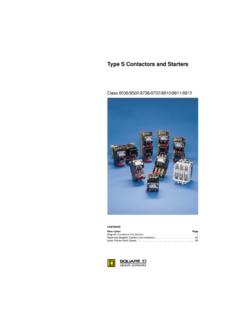
Transcription of LT3 Protection Relays - Steven Engineering
1 LT3 Protection Relays ContentsApplication Information .. 3 Product Selection .. 4-5 Product Characteristics .. 6-8 Operation .. 9 Dimensions and Wiring Diagrams .. 10 File 91102 1997 Square D All Rights Reserved10/973 1997 Square D All Rights Reserved10/97 Application Information - Thermistor Protection Relays Provide additionalmotor Protection and should be used to supplement a conventional currentsensing overload thermistor Protection units continuously monitor the temperature of the machines to be protected (motors,generators, etc.) by means of PTC thermistor probes embedded in the machine the nominal operating temperature of the probes is reached, they convert the rapid increase in resistance into aswitching function which can be used to switch off the machine or signal a fault (see Thermistor probes below).
2 Accidental breaks in the supply circuits of the thermistors are also compatibilityConforming to "Electromagnetic compatibility" directive, draft standard EN to electrostatic discharge (conforming to IEC 1000-4-2)Level 3 Resistance to fast transients (conforming to IEC 1000-4-4)Level 3 Susceptibility to electromagnetic fields (conforming to IEC 1000-4-3)Level 3 Surge resistance - 8/20 (conforming to IEC )Level 4 Immunity to microbreaks and voltage drops (IEC 1000-4-11)Suitable for use with variable speed controllersThermistor probesThermistor Protection Relays provide additional motor Protection and should be used to supplement a conventionalcurrent sensing overload of most commonly used PTC thermistor probes: from 90 to 160 C, in steps of 10 R = f ( ), characteristic of a PTC thermistor probe is defined by standard IEC choice of PTC thermistor probe to be incorporated in the motor winding depends on the insulation class, the typeof motor and the most suitable location for the probe.
3 This choice is usually made by the motor manufacturer or themotor rewinder, who have all the necessary informationApplication exampleInsulation classNOTT emperature at which rapidof rotating machinesNominalincrease in resistance occursconforming to IEC 34-11-2operatingProbes used for(S1 duty)temperatureAlarmFault C C CA100100110B110110120E120120130F14014015 0H160160170LT3 Protection RelaysApplication Information4 1997 Square D All Rights Reserved10/97 Thermistor Protection To Monitor The Temperature of Motor Windings,Transformer Laminations Relays (without fault memory).
4 Units with automatic reset with thermistor short-circuit detectionVoltageOutputPart NumberWeightcontactkgc115 Hz230 with automatic reset with thermistor short-circuit detectionOn front face : fault and voltage signalling NumberWeightcontactkgc115/230 VN/C + Hza24/48 VN/C + 50/60 V2 aProtection units (with fault memory)Note: Thermistor Protection Relays provide additional motor Protection and shouldbe used to supplement a conventional current sensing overload with manual reset with thermistor short-circuit front face :- fault and voltage signalling LED,- Test and Reset NumberWeightcontactkgc400 VN/C + Hz24/48 VN/C + VN/C + VACN/C + 50/60 VAC2 aLT3 Protection RelaysThermistor ProtectionLT3SE00 MLT3SA00 MLT3SM00M5 1997 Square D All Rights Reserved10/97 For use with LT3 Protection RelaysPTC Thermistor ProbesDescriptionNominalSoldPart NumberWeightoperatinginkgtemperaturelots of CIntegrated triple.
5 LT3 Protection RelaysDA1 TTiiiDA1 TSiii6 1997 Square D All Rights Reserved10/97 Control Circuit CharacteristicsTypeLT3 SELT3 SALT3 SMResistanceTripping number of probesused in seriesProbes 250 to 25 666 Voltage at terminals inNormal operation, R=1500 V< < < thermistor circuitConforming to IEC 34-11-2, R=4000 V< < < detectionOperating threshold < 20< 20< 20 Distanceft98513121640 Connection of probes to the LT3m300400500 1000 Minimum size of conductorsAWG18 AWG18 AWG18 mm2 (min) to 2 x 2 mm2 (max)Electrical characteristics of the output relay contactsContact typeSingle voltage or dual voltage1 N/C1 N/C + 1 N/O1 N/C + 1 N/OMulti-voltage 2 C/O2 C/ORated insulation voltageVc 500 Maximum operational voltageVc250 (c400 V for LT3SM00V)Rated impulse withstand voltageU thermal currentA5 Operational powerAt 220 VVA100 for million operating cyclesBreaking capacityCos = - 24, 48, 127, 240 VVA500500500a L/R = 25 msW505050 Cabling (Box Lug connector)Without cable endAWGup to 2 #18 to #14 AWGfor flexible or solid mm2 (min) to 2 x 2 mm2 (max)
6 Tightening torquein probe characteristicsTypeDA1 TTiiiDA1 TSiiiConforming to standardsIEC 34-11-2 Mark AUL 508/CSAR esistanceAt 25 C 3 x 250 in series250 Rated operational voltage (Ue)Per probeVa V maxa V maxRated insulation voltage (Ui) of connecting probesmm250 Between probes andmotor terminal platem11LT3 Protection RelaysCharacteristics7 1997 Square D All Rights Reserved10/97LT3 Thermistor Protection Relay CharacteristicsTypeLT3 SELT3 SALT3 SMReset methodAutomaticAutomaticManual/Automatic Fault indication On front faceOn front faceof unitof unitand remoteand remoteFault test By pushbuttonon front faceof unitInterchangeabilityLabel Mark A Label Mark A Label Mark A to IEC 34-11-2to IEC 34-11-2to IEC 34-11-2 EnvironmentUL508/CSAUL508/CSAUL508/CSAC onforming to standardsIEC
7 34-11-2 IEC 34-11-2 IEC 34-11-2 VDE 0660 VDE 0660 VDE 0660 ApprovalsCSA, ULCSA, UL, PTB, RINA, BV, GL, DNV, LROSD egree of protectionIP 20 conforming to IEC 529, VDE 0106 markingLT3Si Protection units have been designed to comply with the basicrecommendations of European directives relating to low voltage andEMC. Therefore, LT3Si products bear the European Community air temperatureStorage F40 to 185around the device C- + 85 Conforming to IEC 68-2-1/68-2-2 Operation F-10 to 140 C- + 60 Maximum operatingWithout deratingm1500altitudeWith deratingUp to 3000 m, the maximum permissible ambient air temperature foroperation (60 C) must be reduced by 5 C per additional 500 mabove 1500 mVibration resistanceConforming to IEC g ( Hz)1 g ( Hz)Shock resistanceConforming to IEC 68-2-275 g (11 ms)
8 Operating positionsIn relation to normalAnywithout deratingvertical mounting positionPower supply circuit characteristicsRated control circuitc 50/60 Hz Single voltageV115 or 230 400voltage (Uc) Dual voltage 115/230115/230, 24/48of Nominal Voltage Multi-voltage Single voltageV24 Uc Dual voltage 24/4824/48 Multi-voltage consumptionSealedcVA< < < < 1< 1< 1LT3 Protection RelaysCharacteristics8 1997 Square D All Rights Reserved10/97LT3 Thermistor Protection Relay CharacteristicsLT3S Protection unit/thermistor probe combinationGuaranteed operating zones.
9 Examples with 3 probes type DA1 TTiii (250 to 25 C) in series, conforming toIEC 34-11-2, mark , LT3SA, LT3SM Protection units13 probes type DA1 TTiii (250 to 25 C) in seriesNOT : Nominal operating temperatureProtection unit trippedProtection unit set10 000310010010-20 NOT - 20 CNOT - 5 CTNFNOT + 5 CNOT + 15 C20750100016502700150001 Reset zoneTrip zoneLT3 Protection RelaysCharacteristicsResistance(ohms)Tem perature( C)Trip zone onprobe short-circuit9 1997 Square D All Rights Reserved10/97 LT3 Thermistor Protection RelaysLT3SA Protection RelaysStartingThe LT3SA is normally energized and its internal relayis in the pre-energized motor is started by operating pushbutton M andautomatically held in by K (3-wire control circuit).
10 Thermal faultThe rapid increase in resistance of the PTC probes atthe moment their temperature reaches the nominaloperating temperature is detected by the LT3SA unitand causes the relay to drop out; indicator H comes on,as does the built-in indicator on unit K drops out and pressing button M has noeffect. Falt indicator will illuminate when the thermistorrelay the motor cools it reaches the reset threshold, 2 to3 C below the nominal operating temperature. Therelay resets and the motor can be started by pressingbutton Protection RelaysOperation is very similar to that described above, exceptfor the following:ResetAfter tripping on thermal fault and cooling to the resetthreshold, the Test/RESET button on the unit (R1) or aremote reset button (Rd) must be pressed to energizethe fault is therefore memorized, even though thetemperature of the probes has dropped to well belowthe reset circuitSince the relay has 2 separate contacts.