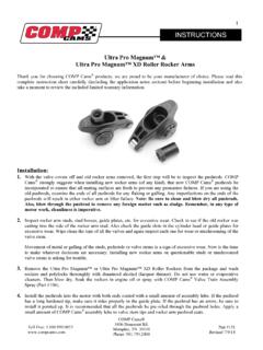
Transcription of Magnum Roller Rocker Arms™ Installation Instructions
1 Magnum Roller Rocker Arms . Thank you for choosing comp cams products; we are proud to be your manufacturer of choice. Please read this instruction sheet carefully before beginning Installation , and also take a moment to review the included limited warranty information. Installation Instructions 1. First read the special Instructions on page 3. 2. With the valve covers off, and old Rocker arms removed, the first step will be to inspect the pushrods. comp cams strongly suggests when installing new Rocker arms (of any kind), that new comp cams pushrods be incorporated to ensure that all mating surfaces are fresh to prevent any premature failures. If you are using the old pushrods, examine the ends of all pushrods for any flaking or galling.
2 Any imperfections on the ends of the pushrods will result in either Rocker arm or lifter failure. Be sure to clean and blow-dry all pushrods. Also, blow through the pushrod to remove any foreign matter such as sludge. Remember, in any type of motor work, cleanliness is imperative! 3. Inspect Rocker arm studs, pedestals, etc. for excessive wear. Check to see if the old Rocker was cutting into the side of the Rocker arm stud. Also check the guide slots in the cylinder head or guide plates for excessive wear. Wipe clean the tops of all the valves and again inspect each one for wear or mushrooming of the valve stem. Movement of metal or galling of the studs, pedestals or valve stems is a sign of excessive wear.
3 Now is the time to make whatever decisions are necessary. Installing new Rocker arms on questionable studs or mushroomed valve stems is asking for trouble. 4. Remove the Magnum Roller Rockers from the package and wash balls, rockers, and nuts thoroughly with soap and hot water or denatured alcohol (lacquer thinner.) Then blow dry. 5. Install the pushrods into the motor. If the pushrod has a long hardened tip, make sure it rides properly in the guide plate. If the pushrod has an arrow, be sure to install it pointing up. It is recommended that all the pushrods be pre-oiled through the pushrod holes. Apply a small amount of comp cams assembly lube to valve stem tips and Rocker arm pushrod seats.
4 6. Install Rocker arm on Rocker stud. Pay special attention to the pushrod and Rocker arm positioning. Be sure that the pushrods are seated in the lifter and Rocker arm seats. Apply a liberal coating of comp cams assembly lube to the Rocker arm ball and position it on the Rocker stud, flat side up. Install adjusting nut, do not tighten the adjusting nut until you go through the proper sequence of lifter adjustment. Install the remainder of Rocker arms in this manner. Part #250. Revised 12/11/03. 7. After carefully checking to be sure all pushrods are seated in the lifter and Rocker arm, it is time for valve lash adjustment. 8. By installing the crankshaft dampener bolt back into the snout of the crankshaft, turn the engine over by hand in the direction of its running rotation until the exhaust pushrod begins to move upward to open the valve.
5 This ensures that the lifter is on the base circle, and the intake valve is ready to be adjusted. Hydraulic Lifter cams : Tighten the adjusting nut until all the slack is taken out of the Rocker arm and pushrod. By lightly turning the pushrod with your fingers as you tighten the adjusting nut, you will discover or feel a point at which there will be slight resistance. At this point, you have taken all the excess slack out of the pushrod. You are now at what we refer to as zero lash. Turn the adjusting one-half turn more. This will give you the ideal pre-load of the Rocker arm, pushrod, and lifter. Following this procedure, carefully adjust all intake valves. Solid Lifter cams : Consult cam spec card or cam manufacturer for correct lash specifications.
6 Tighten adjusting nut, while proper feeler gauge is between Roller tip and valve, to the point at which there is a slight drag when moving the feeler gauge. On solid lifter cams you wish to use 4602-16 (3/8 ) or 4603-16 (7/16 ) polylocks. Following this procedure, carefully adjust all intake valves. 9. Hydraulic Lifter cams : To adjust exhaust valves, turn the engine over until the intake pushrod moves all the way up. Rotate past maximum lift, approximately one-half to two-thirds of the way back down. The lifter is now on the base circle and the exhaust valve can be adjusted. Rotate the exhaust pushrod with your fingers and begin to tighten the exhaust adjusting nut. When you feel the resistance on the pushrod, you are at zero lash.
7 Tighten the adjusting nut one-half turn more. Go through the exhaust valves and repeat the procedure carefully. Now all of the valves are adjusted with the proper pre-load. Solid Lifter cams : To adjust the exhaust valves, turn the engine over until the intake pushrod moves all the way up. Rotate past maximum lift, approximately one-half to two-thirds of the way back down. Tighten adjusting nut, while proper feeler gauge is between Roller tip and valve, to the point at which there is a slight drag when moving feeler gauge. Following this procedure carefully adjust all exhaust valves. 10. Before the valve covers are installed, be sure to pour engine oil on the Rocker arm balls and Roller tips.
8 This will be extra assurance that the Rocker arms will have adequate lubrication until the oil travels up from the motor. Caution: The following must be checked before operation! Old pushrods should not be used. Immediately upon startup Rocker arms must have adequate oil supply. Check pushrod to cylinder head slot clearance. Check Rocker arm to valve spring retainer clearance. Check for valve spring coil bind. If this occurs, the correct spring must be installed. In most cases, the maximum open spring pressure is 350lbs. Be sure to check for proper Rocker geometry. Special Instructions Important! 1. The use of old pushrods may result in pushrod or Rocker arm failure. It is necessary that you install new pushrods with your new Magnum Roller Rocker Arms to ensure your Rocker arm warranty.
9 Pushrod ends have a mated surface to the Rocker arm ball socket, much like a cam and lifter mate to each other. This why used pushrods cannot be run with new Magnum Roller Rockers . 2. On racing applications with dual springs, the Rocker arms should be removed and inspected after the first hour of running time. The recommended maximum open valve spring pressure is 350lbs. 3. Never use Magnum Roller Rockers with solid Roller lifter camshafts. 4. In most cases Magnum Roller Rockers fit under stock valve covers without any clearance problems. However, you should always check for interference, especially if you have cast aluminum valve covers. AMERICAN MOTORS. '66-'90 V-8 290-401 Part # 1442.
10 Before installing Magnum Roller Rockers , cylinder heads must be machined to accept screw-in studs and guide plates. For high valve lift (.500 +) applications, longer pushrods may be required to correct Rocker arm geometry. Remember, valve tip height, block deck height, cam base circle and head surface all affect the pushrod length required. CHEVROLET. '65-Present 396-454 Part # 1411. When installing Magnum Roller Rockers , check your new pushrods to make sure they fit your guide plates. Chevrolet has used 3 different pushrod diameters on production big blocks (5/16 , 3/8 , 7/16 ). Be sure to check for valve spring coil bind, as this is a major problem area for big block Chevrolets. These Rocker arms require machining if used on 1991 and newer 454's.