Transcription of Ford Timing Set Installation Instructions
1 ford Timing Set Installation Instructions Thank you for choosing comp cams products! We know you have options in valve train component selection and we are proud to be your manufacturer of choice. Please read this instruction sheet carefully before beginning Installation , and also take a moment to review the included limited warranty information. Engine Application High Energy Magnum Hi-Tech ford V6, 144-200 3223. ford V6, 171 (2600-2800cc) 3236. ford V8, 255, 289, 302 & Boss 302, 1965-1988 2120 3120. ford V8, 289-351W & Boss 302, pre 1972 3220. ford V8, 302-351W, 1972 & up 3230. ford V8, 352-428, 1964-1974 3208 2108 3108. ford V8, 351C, 351M, 400M, 1970-1982 3221 2121 3121. ford V8, 429-460, 1968-1971 3222 2122 3122. ford V8, 429-460, 1972-1987 2130 3130.
2 ford V8, 429-460 w/nine keyway crank gear 2134*. ford V8, 351W, 351W , 1969- 84 2135 3135. ford V8, 302 , 1980-March 21, 1984 2131 3131. ford V8, 302, 351W, March 22, 1984-1992 2138 3138. Notes: * #2120 or #3120 should not be installed on 351W engines as they are designed for 255, 289, 302 or Boss 302 engines. * If installing part #2120 or 3120 a one-piece fuel pump eccentric ( ford #C3AZ-6287-B) must be used. * If installing part #2135 or 3135 a two-piece fuel pump eccentric must be used. * Uses a link belt type Timing chain, not a double roller. Thrust Bearings Part # Description 3108 TB ford 390-428 thrust plate and bearings 3120 TB ford 289-351W thrust plate and bearings. Direct replacement for OEM cam plate single bearing. 3135 TB ford 289-351W HP thrust plate and bearings.
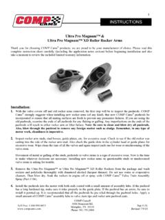
3 Machining and tooling required 3122 TB* ford 351C, 429-460 thrust plate and bearings Part #179. Revised 6/27/05. Tools and supplies needed: 1. Basic hand tools as required for your particular camshaft and balancer bolts 2. Torque wrench 3. Pro Cam Lube (part #153 or #154) or suitable replacement 4. Camshaft Degree Kit (part #4796 including degree video). 5. Crankshaft Socket (part #4798 for ford 302-351W, 429-460). 6. Thread locking compound 7. Engine repair manual for your particular engine The following Instructions begin after the Timing cover and old Timing set have been removed. Installation Instructions 1. Clean everything! Make sure that the engine mounting surfaces and your new Timing set have been thoroughly cleaned with a good solvent.
4 2. If you are using a Timing set with three keyways, select the appropriate keyway for your camshaft Timing specifications. comp cams recommends the standard Timing position for most applications. This position uses the round or O Timing and keyway marks. Standard Timing Location: This is the same as original setting. Use keyway and crankshaft gear tooth marked O . 4 Degree Advance: Use keyway and crankshaft tooth marked . Note: The or advanced position should not be used without degreeing the camshaft. Many camshafts have the proper advance built in. Advancing the cam will reduce intake valve to piston clearance and increase exhaust piston to valve clearance. 4 Degree Retard: Use keyway and crankshaft gear tooth marked . Note: The or retarded position should not be used without degreeing the camshaft.
5 Many cams have the proper advance built in. Retarding the cam will reduce exhaust valve to piston clearance and increase intake piston to valve clearance. 3. Install your lower Timing gear on the crankshaft making sure that the Timing marks are facing out toward you. 4. Now that the lower Timing gear has been installed check the Timing mark alignment in your engine manual. Rotate the crankshaft using your crankshaft socket until the Timing mark on the gear is in the proper position (12 o'clock). For 240-300 6 cyl. see Note 1 before proceeding! 5. If your engine is equipped with a camshaft retaining plate or thrust plate, it should be installed at this time. Note that many ford thrust plates are marked back bottom . Before final Installation check to make sure that the thrust plate is fitted correctly.
6 351W owners see Note 2 before proceeding! 6. Temporarily install your camshaft Timing gear and rotate the camshaft until the Timing mark on the camshaft gear is in the proper position per your engine manual Instructions (6 o'clock). 7. Remove the camshaft Timing gear and loop the chain over the camshaft gear. Lift the camshaft gear into place on the camshaft. Install the fuel pump eccentric and camshaft bolt or bolts (finger tight for now). 289, 302 & 351W owners see note 3 before proceeding. 8. Check your manual again for the proper Timing mark positions and make sure that both camshaft Timing mark (6 o'clock) and crankshaft Timing mark (12 o'clock) are correct. If this procedure is missed by even one tooth, engine damage can result.
7 9. For a more accurate Installation we recommend that you degree your cam at this time using the Instructions and video provided with your comp cams Degree Kit, Part #4796. 10. To ensure that you have the right clearances and combination of parts you must check the camshaft end play. To check camshaft end play, the cam first must be moved completely to the front of the engine, against the back of its retaining plate. Do so by pulling the cam gear forward gently until it stops against the plate. Use a feeler gauge to check the clearance between the front of the camshaft retaining plate and the back of the Timing gear. The proper clearance should be between .004 and .008 . End play can also be checked with a dial indicator on the front of the cam gear while the cam is moved backwards and forwards completely in the engine.
8 11. Refer to your repair manual again for proper torque specifications and torque your camshaft bolt or bolts. Caution: If camshaft bolts loosen up, severe engine damage can result. A good thread locking compound should be used on all bolts. 12. Check to be sure that the back side of the chain does not touch the front face of the block any where along the entire length of the chain. Grind the block to obtain clearance if necessary. Do not modify the chain. 13. Make sure that the engine oil has a clear path to the Timing set through the lifter valley drain holes or some other means. Timing sets require plenty of oil to survive. When increasing Timing chain speed (RPM), lubrication must also increase. 14. Before installing the Timing cover and gasket, pour plenty of pro cam lube (part #153 or 154) or oil over the Timing set.
9 The proper lube will protect your Timing set during final assembly and start up. 15. Install your Timing cover, harmonic balancer and torque your balancer bolt. Note 1: ford has used two different styles of camshaft Timing gear sprockets, as seen in figures 3 and 4. The camshaft sprocket in figure 3 requires the use of a spacer. The camshaft sprocket in figure 4 does not require a spacer as it is integrated into the sprocket. Be sure to check your camshaft sprocket to see which unit you have before installing. Note 2: Because of the extra thickness required on high performance Timing gears, many 351W engines require the removal of material from the camshaft retaining plate as shown in figure 1, or the use of an earlier year model 302 retaining plate as shown in figure 2.
10 If this material is not removed, the darkened area shown in figure 1 will rub against the back side of the camshaft Timing gear. The camshaft retaining plate should not come into contact with any part of the camshaft gear sprocket area. The only contact area between the camshaft retaining plate and the Timing gear should be in the hub area. Note 3: If you are working on a 289, 302, or 351W and using a two-piece fuel pump eccentric, great care should be used in checking the clearance between the camshaft dowel pin and the fuel pump eccentric drive tab. If the dowel pin is too long it will come into contact with the fuel pump eccentric tab and keep it from seating against the camshaft gear. There should be clearance between the dowel pin and the eccentric tab, and the dowel pin should not extend beyond the camshaft snout.