Transcription of Making a Coil Winder (mostly from the junk box)
1 16In the past I have rewound series field coils using a variable speed battery drill held in a vice. These fields have relatively few turns and a largish wire size but this radio used a shunt coil with lots of turns of 38-gauge wire. Obviously for it and the inter-stage transformer something better than the drill in the vice was RequirementsThe field coil in question weighed three pounds and being as it used a bobbin without cheeks this was almost all copper wire. It and the feed coil, being so heavy, were going to need spindles supported at both ends. I knew from experience, with the drill in the vice, how much better it would be to have a foot pedal for start and stop and control of speed. Later I was to find that some sort of traverse, for the feed wire, made for a much more uniform winding.
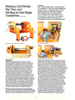
2 For the field coil I wouldn t really need a turns counter, just fill a new bobbin, but for the inter-stage transformer this would not be the case. Finally, being as I wouldn t use it all that much I wanted it to be low cost with parts mainly from the junk ll keep this description relatively simple; in the event that anyone should want to make a similar machine then the pictures should tell most of the story. However, I have given some dimensions of my effort, which should assist another constructor. Fortunately I had variable speed battery drill with a well worn chuck and a tired battery. The chuck no longer gripped drills sufficiently for high torque jobs but was fine for coil winding as not a lot of torque is needed. The battery would hold charge long enough and I could substitute batteries from other drills (the battery holder is less specific than an actual drill).
3 Once stripped down the chuck, gearbox and motor assembly were mounted as shown in the pictures. The gearbox and motor do come apart so both need to be individually clamped. The clamps were made from scraps of plywood having a hole cut through them with a hole-saw. Once cut in half, across the hole, I put a locating key (a lost head nail with its head proud) which fits into slots in both items. Then long thin wood screws were used to tighten the clamps. In the case of the motor clamp this is also screwed to the side panel. The gearbox was best set for screw driving as it gives a much smoother start although the maximum speed is less. In practice, most drills in this mode are specified at 400 RPM, which is adequate. I included a cover over the motor end to protect it upon entry and exit from the loft where it will live between jobs.
4 As can be seen the trigger and speed control are built into a simple housing, with the control best operated without a slipper! The battery simply drops through the hole with the rewired connector being attached as this is done. The drill takes three to four amps so I used a large wire gauge between it and the foot control. The only heavy wire I had was some spare cooker cable so I stripped the red and black wires from that. At first the items were hard wired but this got inconvenient so I included a plug and socket (US line types). The traverse for the wire feed is the piece of chrome plated tube, scrap from an old shower installation. It s simple and how I use it is described later. Well, you didn t really expect me to come up with a gear driven backwards and forwards mechanism as used on Pro.
5 Machines did you. The frame was made from15 mm thick plywood and dimensions (which would vary with the drill used) are: overall length , depth , height inches excluding motor cover and turns counter. The feed wire spindle is set back from the front by inches and is inches up from the inside base. The traverse tube is 2 inches back from the feed wire spindle and inches up from the inside base. The motor spindle is 3 inches in from the rear and inches up from the inside base. The centre holes, for the feed and take up spindles, were drilled with the side panels clamped together of course. The Making a Coil Winder (mostly from the junk box) part 1by Gary Tempest Improvements, modifications and winding an interstage transformer in part 2 (to follow)Why make a coil Winder ?
6 Well with old radios eventually you come up against open circuit components and for the one I was restoring this was the case. It had an open speaker field coil and push-pull inter-stage transformer. Yes! There are ways around re-winding such as substitution of permanent magnet speakers and other transformers. But this is really fixing a radio up and isn t restoration. It s so much more satisfying to rewind and put the set back as it was tube is fixed in place by cutting two plywood discs, that fit the inside of the tube, and screwing them to the side panels. Initially I only had a hole in the left-hand side piece for the motor spindle and therefore made this side relatively quickly detachable. It is held to the bottom with furniture blocks having a machine screw.
7 However, in practice when trying to fit the bobbin for the new wound coil it turned out to be very awkward. The solution was to slot the hole and fit an easily removed bearing cap . All bearing holes were lubricated with lithium grease. The feed and motor spindles were cut from easily obtainable 10 mm studding. I found out that the feed and new coil bobbin need to be securely fixed so I used a wing and a full nut locking one against the other. I did the same for the end of the removable spindle for the feed bobbin and locked these up hard before starting. It s surprising how things become loose with the inevitable vibration. Slippage on the wound coil only gives a few more indicated turns, a jam on the feed means the wire breaks!Turns CounterIntroductionI looked around for some time for a rotary counter (tape recorder etc) but did not find anything.
8 Anyway they may have been difficult to drive requiring greater mechanical input than electronic. There are electro-magnetic counters but they are relatively expensive and of course they still need some sort of switch, operated by the shaft upon which the coil is mounted, to provide input. So I turned to 4000 Series Cmos, which is now obsolete although fortunately still readily available. It s excellent for low-speed applications with good noise immunity. I was lucky enough to work with it (and most other logic families) but it s now getting on for a couple of decades since I did so. I enjoyed my trip down memory lane whilst designing this useful and inexpensive circuit. It can be built for a few pounds but I had most of the components anyway. The CircuitIf you have done much work with Cmos logic then this circuit will be simple and you will rapidly move on.
9 If not then I expect it will look daunting, but maybe with some explanation all will become clear. This 4000 series of Cmos (Complimentary Metal Oxide Semiconductor) uses p-type and n-type Mos Fets to achieve its logic functions. When looking at the schematic the first thing to appreciate is that I have only drawn one sample counter output and its associated buffer to LED 5. All the rest are repetitions and given in the running out lists below. This is much easier to do than a full drawing and how we convert that information for wiring anyway. The counter is two 4024, 7 stage ripple counters in cascade. The counter outputs are buffered and inverted (3 off 4049 devices) to light LEDs for the output display. The counters work in binary and so a little arithmetic addition (or a scientific calculator) is needed to convert the LED display into decimal for the number of decimal values for each LED is given on the label that is glued below the display.
10 So as an example, say LED s 8, 5, 4, 2 and 1 are lit then just add 128, 16, 8, 2 and 1 to give 155 turns. Alternatively, enter the binary number into a scientific calculator that will do the conversion. You put in 10011101, with unlit LED s counting as 0, and up comes155. Unlit LED s, of higher order than the last one lit, don t count as they wouldn t if the display was in decimal. It has a maximum count of twice the last LED minus one, which equals 16383. If you go round the clock its simple to make a note (mental if you trust it!) and just add this to the total. This may seem cumbersome but I was used to counting in binary and it is something you quickly get the hang of. For an occasional use coil Winder it is good enough. Another way to use it is to work out what LED s will be lit for the number of turns needed first.