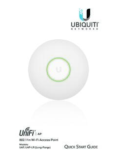
Transcription of Managed PoE+ Gigabit Switch with SFP
1 Managed PoE+ Gigabit Switch with SFPM odels: US-24-250W, US-24-500W1 GIntroductionThank you for purchasing the Ubiquiti Networks UniFi Switch with SFP. The UniFi Controller software and User Guide are available for download at: Quick Start Guide is designed to guide you through the installation and show you how to access the Configuration Interface. This Quick Start Guide also includes the warranty terms, and is for use with the UniFi Switch with SFP, model US 24 250W or US 24 500W. (The hardware description and installation instructions are the same for both models.) Package Contents1 GUniFi SwitchManaged PoE+ Gigabit Switch with SFPM odels: US-24-250W, US-24-500W1 GPower CordMounting Screws (#10 32 x 5/8", Qty.)
2 4) Cage Nuts (#10 32 x 5/8", Qty. 4)Quick Start GuideSystem Requirements Linux, Mac OS X, or Microsoft Windows 7/8 Java Runtime Environment (or above) Web Browser: Mozilla Firefox, Google Chrome, or Microsoft Internet Explorer 8 (or above)TERMS OF USE: All Ethernet cabling runs must use CAT5 (or above). It is the customer s responsibility to follow local country regulations and indoor cabling Topology Requirements A DHCP enabled network for the UniFi Switch to obtain an IP address (connected devices will also obtain IP addresses after deployment) A management station running the UniFi Controller software, located either on site and connected to the same Layer 2 network.
3 Or off site in a cloud or NOCorUniFi SwitchUniFiSecurityGatewayInternetUAP-AC UAP-PROLANWANO -SiteCloud/NOCOn-SiteManagementStationNe twork HealthwwwWANLANWLANVOIPwwwWANLANWLANVOIP IPDNSGATEWAYACTIVE CLIENTSDOWNUPSWITCHESUSERSGUESTSDOWNUPAP SUSERSGUESTSDOWNUPPHONESEXTENSIONCALLS INCALLS SITED efaultREFRESH RATE2 minutesNetwork HealthwwwWANLANWLANVOIPwwwWANLANWLANVOIP IPDNSGATEWAYACTIVE CLIENTSDOWNUPSWITCHESUSERSGUESTSDOWNUPAP SUSERSGUESTSDOWNUPPHONESEXTENSIONCALLS INCALLS SITED efaultREFRESH RATE2 minutes1 GUAP-Outdoor+Sample Network DiagramAll UniFi devices support off site management controllers. For setup details, refer to the User Guide on the website: OverviewFront Panel System LED1 GSystemStateStatusWhiteFactory defaults, waiting for White/BlueDevice is busy; do not use or unplug it.
4 This usually indicates that a process such as a firmware upgrade is taking integrated into a network and working BlueThis is used to locate a device. When you click Locate in the UniFi Controller software, the System LED will flash blue. The software will also display the location of the UniFi Switch on the Panel Port LEDs1 GRJ45: PoERJ45: Speed/Link/Act1 GSFP: Speed/Link/ActLEDS tateStatusRJ45 1 24 PoEOffNo PoEAmberIEEE PassiveSpeed/Link/ActOffNo LinkAmberLink Established at 10/100 Mbps Flashing Indicates ActivityGreenLink Established at 1000 Mbps Flashing Indicates ActivitySFP 1 2 Speed/Link/ActOffNo LinkGreenLink Established at 1 GbpsFlashing Indicates ActivityFront Panel Ports1 GRJ45 1-24 SFP 1-2 PortDescriptionRJ45 1 24RJ45 ports support Power over Ethernet (PoE) and 10/100/1000 Ethernet 1 2 Hot swappable SFP ports support 1 Gbps Panel ButtonReset1 GButtonDescriptionResetThis button serves two functions for the UniFi Switch : Restart Press and release the Reset button quickly.
5 Restore to Factory Default Settings Press and hold the Reset button for more than five seconds.*640-00083-03*640-00083-03 Back PanelCONSOLEM ounting HolesPowerMounting HolesConsoleNote: The Console port is reserved for future PanelsVentilation HolesFansInstallation Requirements Phillips screwdriver Standard sized, 19" wide rack with a minimum of 1U height available For indoor applications, use Category 5 (or above) UTP cabling approved for indoor use. For outdoor applications, shielded Category 5 (or above) cabling should be used for all wired Ethernet connections and should be grounded through the AC ground of the power recommend that you protect your outdoor networks from the most brutal environments and devastating ESD attacks with industrial grade shielded Ethernet cable, TOUGHC able , from Ubiquiti Networks.
6 For more details, visit: : Although the cabling can be located outdoors, the UniFi Switch itself should be housed inside a protective Installation1. Connect the Power Cord to the Power port of the UniFi Attach the UniFi Switch to the rack using the four Mounting Screws. (If the rack has square slots, then use the Cage Nuts with the Mounting Screws.)1 3 5 7 9 11 13 15 17 19 21 222 4 6 8 10 12 14 16 18 20 22 24 SFP1 SFP2 Note: Keep 20 mm of clearance next to the ventilation holes for adequate Connect the other end of the Power Cord to a power Ethernet1.
7 Connect an Ethernet cable from your computer or host system to any port of UniFi 3 5 7 9 11 13 15 17 19 21 222 4 6 8 10 12 14 16 18 20 22 24 SFP1 SFP22. Connect Ethernet cables from the Ethernet ports of your devices to the other numbered ports of the UniFi : The PoE settings for ports 1-24 are set to auto sensing PoE+ by default, so devices can be plugged in and automatically receive PoE.
8 For instructions on how to enable 24V passive PoE, refer to the Configuring PoE Settings SFP PortsTo use an SFP port:1. Remove the protective plug covering the SFP port. 2. Plug a compatible fiber module into the SFP 3 5 7 9 11 13 15 17 19 21 222 4 6 8 10 12 14 16 18 20 22 24 SFP1 SFP21000 Mbps SM/SC 20KM DDMTx1550nm/Rx1310nm3.
9 Connect a fiber optic cable to the fiber module. Then connect the other end of the cable to another fiber 3 5 7 9 11 13 15 17 19 21 222 4 6 8 10 12 14 16 18 20 22 24 SFP1 SFP250 For information about compatible fiber SFP modules, visit: InstallationDownload and install the latest version of the UniFi Controller software at and follow the on screen : If you already have UniFi Controller or higher installed, skip to the section, Adopting the UniFi you have installed the software and run the UniFi Installation Wizard, a login screen will appear for the UniFi Controller management interface.
10 Enter the admin name and password that you created and click Login. You can manage your network and view network statistics using the UniFi Controller management interface. To adopt the UniFi Switch , proceed to the Adopting the UniFi Switch information on configuring and using the UniFi Controller software, refer to the User Guide on the website: the UniFi Switch1. From the UniFi Controller dashboard, click DEVICES in the left menu On the Devices screen, locate the UniFi Switch in the list of devices under the Name/MAC Address column. To adopt the UniFi Switch , click The System LED on the UniFi Switch will turn blue to confirm that it has been successfully configure PoE settings, proceed to the Configuring PoE Settings PoE SettingsThe PoE settings for ports 1-24 are set to auto sensing PoE+ by default, so devices can be plugged in and automatically receive : Before activating 24V passive PoE, ensure that the connected device supports PoE and the supplied On the Devices screen, locate the UniFi Switch in the list of devices under the Name/MAC Address column.