Transcription of MANUAL/AUTOMATIC TRANSMISSION 2-BUTTON (AS …
1 M A N U A L / A U T O M A T I C T R A N S M I S S I O N 2 - B U T T O N. R E M O T E S T A R T E R W I T H V I R T U A L T A C H S Y S T E M. ( A S P R G - 1 0 0 0 C O M P A T I B L E ). QUICK INSTALLATION GUIDE. Table of Contents manual or automatic TRANSMISSION setup 1 Multi-speed Tach Programming 5 Push-To-Start 2 Resetting the Module 5 PTS takeover 2 Bypass 5 Hybrid Option 2 SmartStart 5 Entering Programming Mode 2 Testing 6 Programming the transmitter to the module 3 Troubleshooting 7 Entering Programming Options 3 Diagnostics Parking Light Flash Table 7 Programming Options 3 Diagnostic table for start failure. 7 Setting up the TACH 5 Diagnostic table for shutdown.
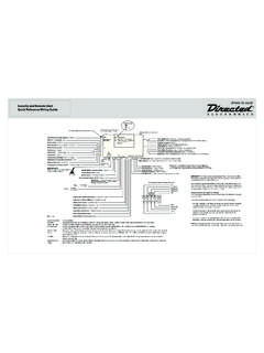
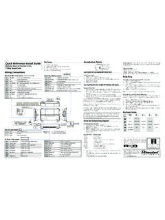
2 7 Virtual Tach adjustment 5 The wiring diagram is at the middle of this guide. The functions of the transmitter are as follows: Remote Function OPTION 1 Remote Function OPTION 2. button : STOP button : LOCK/UNLOCK. button : START/STOP button : START/STOP. button & BUTTONS (together): TRUNK button & BUTTONS (together): TRUNK. manual OR automatic TRANSMISSION SETUP. This module may be installed on vehicles with manual or automatic transmissions . It is originally configured for manual transmissions . If the vehicle you are working on is automatic , it is mandatory to make a few quick and easy modifications before the unit is connected. In the event that the configuration requires changes afterwards, a complete reset (page 5) will be necessary before those changes become effective.
3 To install this unit in a vehicle with a manual TRANSMISSION : 1. Make sure the Yellow loop on the PC board is connected (default). 2. Connect the Orange handbrake wire, located on the 12-pin harness, to the vehicle handbrake circuit (-). 3. Connect the Blue/White (+) OR Grey (-) door input wire, located on the 12-pin harness, to the vehicle door pin wire which monitors all the doors of the vehicle (only use 1 of the 2 door trigger inputs). 4. Make sure the Purple TACH wire is wired to a tach source the TACH wire MUST be hooked up when the module is set for a manual TRANSMISSION . 5. Make all your regular connections. 6. Power up the unit by first inserting the 5-pin connector, then the 6-pin connector and finally the 12-pin connector.
4 The parking lights will flash 4 times. 7. When learning the transmitter, the parking lights will flash 5 times quickly. 8. Upon the first successful remote start, the system will lock the TRANSMISSION settings to manual mode. To install this unit in a vehicle with an automatic TRANSMISSION : 1. Cut the Yellow loop on the PC board (Yellow wire). 2. Make sure the Orange handbrake wire is not connected to any of the vehicle circuits (cut and tape). 3. Make all the regular connections. 4. Power up the unit by first inserting the 5-pin connector, then the 6-pin connector and finally the 12-pin connector. The parking lights will flash 4 times.
5 5. When learning the first transmitter, the parking lights will flash 5 times quickly then give 2 slow flashes. 6. Upon the first successful remote start (once the yellow loop has been cut), the system will lock the TRANSMISSION settings to automatic mode. Note: If upon pressing the button the parking lights give 3 slow flashes, make sure that the Orange handbrake wire is not connected, the hand brake is not engaged and that the yellow loop is cut and isolated/taped. Notice The manufacturer will accept no responsibility for any electrical damage resulting from improper installation of the product, be that either damage to the vehicle itself or to the unit.
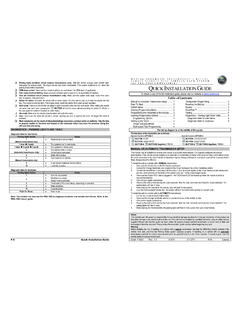
6 This unit must be installed by a certified technician using all safety devices supplied. Please note that this guide has been written for properly trained ProStart technicians: a certain level of skills and knowledge is therefore assumed. Please review the installation guide carefully before beginning any work. Warning Before installing the unit, if installing on a vehicle with a manual TRANSMISSION , test that the OEM Door Switch contacts of the vehicle work well, and that the Parking Brake system operates properly. If installing on a vehicle with an automatic TRANSMISSION , test that the vehicle does not start when the gearshift lever is in the Drive position.
7 If it starts in gear, reset the remote starter to manual TRANSMISSION . Doc#: 111014 Rev. 2011 - CT-3271 - - CP - Canada DIESEL VEHICLE WARNING: The G-Plug wire must not be connected when the brake is detected through D2D. PUSH-TO-START. Disabled by default, PTS mode is a special feature that is intended to facilitate the remote starter installation on most Push-To- Start vehicles. With PTS mode enabled, the remote starter will offer the installer a negative start output (to pulse the vehicle's PTS switch), as well as a (+) brake switch output (no external relay necessary). With PTS enabled, the White/Green wire on the 12-pin harness becomes your negative (-) PTS switch output.
8 It will give a one second output intended to pulse the PTS switch. Also, the Purple crank output becomes your brake switch output (this will turn the brake circuit ON for crank). PTS TAKEOVER. Note: This feature is only available if the button is configured as LOCK or UNLOCK. Without the PTS takeover, pressing the brake pedal after remote starting shuts down the engine (to prevent theft). Here are the new steps for this new Takeover mode: Regular PTS takeover from Remote start: 1. Remote start the engine. 2. Press to unlock and enter the vehicle. 3. Within the pre-programmed time limit ( min or 3 min, see Mode 3), press the brake pedal.
9 PTS takeover from Idle mode: 1. With the engine running, press to engage Idle mode. 2. Exit the vehicle; engine runs without the key. 3. IMPORTANT: After exiting the vehicle, press to lock. 4. Press to unlock and enter the vehicle. 5. Within the pre-programmed time limit ( min or 3 min, see Mode 3), press the brake pedal. HYBRID OPTION. Warning: For automatic transmissions only. This option is disabled by default. It can be enabled in Mode 2 of the programming options. HYBRID mode is a special feature that is intended to facilitate the remote starter installation on most Hybrid vehicles. With HYBRID mode enabled, the remote starter will give a 4-second crank output on its crank wire (It will not rely on VTS to stop the crank cycle).
10 The only way to shorten the 4-second crank output is to program a tach signal to the remote starter. If a tach signal is programmed, the remote starter will act like normal (the HYBRID feature should be used when no tach reference is available from the vehicle or the bypass being used at the time of installation). ENTERING PROGRAMMING MODE. These are the programming buttons: The Hood Pin The Antenna Programming button (the ). The Programming button ( the ). The is located on the side of the module. This push button mimics the hood-pin switch in order to avoid having to get out of the vehicle to press the hood-pin switch. The will work only when the hood pin is installed and the hood is up.