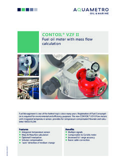
Transcription of Marine application manual - Timer Elcon
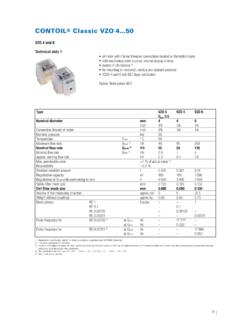
1 Marine application 7-100 e flow meterRotary piston flow meter Reliable, well proven measuring principle Highly accurate measurement Independent of temperature and viscosity Minimum pressure loss No seals (maintenance-free) Insensitive to strong mechanical vibrationsLarge Display with operating buttons Easy to read numbers Clear indication of displayed values Menu-driven operation Simple access to values and parameters Fail-safe operation Parameters change with protected accessTwo programmable electronic outputs Choice of 2 output types- 1 analoque ( mA)- 2 digital out (solid state relay) Choice of 4 functions for each digital output- Volume pulse (totalizer)- Frequency signal (flow rate)- Limit switch (min / max)- Limit switch (State alarm / error)Maximum size chamberTypeflow rateflow rateVZFVZFA*before FMvolumeL/hL/h%%mmcm3 VZF(A) (A) (A) (A) (A) * VZFA type flow meters can be calibrated in pair for SL ( ) and RL ( ) Flow meters are available in DIN, JIS & ANSI flange types and threads1 2 43 5 DCDesign Guidelines Flow sensors are accurate measurement devices, which need some considerations in design and care during installation.
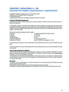
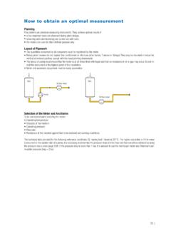
2 Any measuring sensorcan only perform in the optimum range, when it is used within it s specific requirements. Please consider application specific limit PulsationdampersPulsationdampersCONTOIL EngineFilterPulsationdampersTankAuto FilterNegative influencing factorsList of factors which can influence the performance of the flow meter negativelyFurther we want to give some consideration for the whole fuel pipe installation:Direct measurement of consumption for totalizing fuel consumptionDifferential measurement of consumption for real-time and totalizing of fuel consumptionMedium Seawater Acid Cleaning productsMechanical Pulsating pressure Cat fines Pre-Filter mesh sizeSpecification Dimension to small Over temperatureTemperature and density compensationIf fuel oil consumption is compared in mass instead of volume, it is important to know the exact density which is affected by the temperature, hence it's essential toinstall temperature sensors close to the flow meter.
3 Depending on the process it can be around 1% difference in consumption per 10 C temperature recommends to have a density sensor installed to measure it online. If no sensor is available, density values of the bunker report can be calculation for differential measurementASSUMPTION:Standard calibration 1 % accuracy ( contoil VZF): Supply (FM#0) 10 000 l/h 1 % = 100 l/h Return (FM#1) 10 000 l/h 1 % = 100 l/h Max. difference2 % = 200 l/hASSUMPTION:pair calibration % & % accuracy ( contoil VZFA): Supply (FM#0) 10 000 l/h % = 10 l/h Return (FM#1) 10 000 l/h % = 30 l/h Max. % = 40 l/hOffset and differential measurementWith Aquametro fuel Performance Management Systems like: fuel Performance Recorder (FPR), contoil fuel Monitor-S (CFM-S), contoil fuel Monitor-T(CFM-T), these compensation calculations are done automatically, according to DIN calculation with direct and differential measurementASSUMPTIONS: All Flow meter 1 % accuracy M/E consumption4 000 l/hr A/E SL: 3000l/hr.
4 RL: 2600l/hr Circulation pump10 000 l/hr Accuracy M/E with A/E running FM2: 1 % of 3 000 l/hr 30 l/hr FM3: 1 % of 2 600 l/hr 26 l/hr 30 + 26 l/hr = 56 l/hr of 400 l/hr A/E consumption 14 % error FM0: 1 % of 4 000 + 400 l/hr 44 l/hr Total accuracy of M/E = 44 + 56 = 100 l/hr of 4000 l/hr M/E consumption 2,5 % errorSample calculation with 2x differential measurementASSUMPTIONS: All Flow meter calibrated in pair: ( % / accuracy) M/ESL: 10 000 l/hr; RL: 6 000 l/hr A/E SL: 3'000 l/hr; RL: 2'600 l/hr Accuracy M/E with A/E running FM2: of 3 000 l/hr l/hr FM3: of 2 600 l/hr l/hr + l/hr = l/hr of 400 l/hr A/E consumption % error FM0: of 10 000 l/hr l/hr FM1: of 6 000 l/hr l/hr Total accuracy of M/E=10+18=28l/hr of 4 000 l/hr M/E consumption % errorServiceTankFM0M/EMTFM1 ServiceTankFM0M/EMTA/EFM2FM3 BoosterpumpServiceTankM/EMTA/EFM2FM3FM0F M1 BoosterpumpSystem application for Offshore VesselsRMS / FMCC The perfect companion for all work boats Automated data transfer to shore Real time monitoring Easy comparison between vesselsFuel Tank 1 fuel Tank 2A/E 2 *Satellite connection with RMS system onlyGPSA/E 1 CFM-T / RMS*LANM/E 2 M/E 1 SatelliteFMCCT hese applications are suitable for Tug.
5 Riverboats and Offshore vesselswhere information of more than one engine is requiredDFM-BC Simple differential flow measurement 1-2 flow meters in 1 pulse signal output Perfect solution for bridge installation Large displayF-Series 1-2 flow meters with Analog or pulse output Multiple outputs available With or without real temperature compensation Rough housingPumpCONTOIL PulsationdampersPulsationdampersCONTOIL EngineFilterPulsationdampersTankAuto FilterDFM-BCOur solution to monitor the consumption of one engine at the Monitoring SystemCFM-T A multitalented monitoring system for all tugboats and vessels consuming DO Monitor multiple engines Optional: count of Running hours and shaft rpmSimplyfied fuel MonitoringSystem application for Ocean VesselsFPM client SW Data logger and trending software Displays trends up to 6h Receives data from CFM-S, FPR or CFM-TFuel Performance Recorder The heart piece of monitoring equipment Multiple analog inputs Easy handlingShaftmeter State of the art shaft measurement equipment Highly precise sensors.
6 Engine performance and ship efficiencyDOHFOD iesel SwitchViscosity ControllerMixing TubeCONTOIL fuel meterViscomaster Shaft meterGPSFPRFPM Client SWControl ValveLANFuel Performance MangementViscomaster Measure live viscosity and/or density Easy installation or retrofit Virtually maintenance freeViscosity Controller Display live values (viscosity and temperature) Controls the heating cycle Available alarm contactsControl valve The perfect companion to the Viscosity Controller Exact steam or thermal oil flow controlViscosity ControllerViscomaster AMSM ixing TubeControl ValveDiesel Switch Your best friend for ECA zones Automated change-over or blending Protects engine from temperature shocks Homogenizer All the power with possible less consumption. The shearing process is pure mechanical Helps to reduce wear and tearMixingTubeM/EDOHFOD iesel SwitchHomogenizerViscosity SystemDiesel Switching SystemWarranty DisclaimerAquametro guarantees the quality of the product in the context of its General Terms of ship yard, owner or operator will be liable for the correct installation as well as the appropriatehandling of the equipment upon its receipt.
7 Please observe the application -, mounting- and operation- instructions! Use the unit exclusively for its designed purpose. Maintain the unit and service it according to prescriptions. Use accessories only if their applicability is technically safe. Warranty shall not cover in particular the following cases: Inadequate installation works (please follow installation instructions) Unsuitable or improper use Faulty or negligent treatment Excess load Unsuitable operating equipment Natural wear and tear Product has been opened Faulty assembly or start-up by the customer or third parties Improper maintenance Chemical, electronic or electrical influences Corrosive media Excessively high media and/or ambient temperatures Broken separating plates due to missing pulsation dampers Blocked flow meters due to missing strainers before the fuel meters .
8 Force majeureHEAD OFFICE:AQUAMETRO AG Ringstrasse 75CH-4106 TherwilPhone +41 61 725 11 22 Fax +41 61 725 15 (CHINA) PTE LTD AQUAMETRO Japan AQUAMETRO KOREA LTD AQUAMETRO ( ) PTE LTD AQUAMETRO ME JLT 190 Woodlands Industrial Park E5 1-18-4, Nakane #501, Centum IS Tower, 190 Woodlands Industrial Park E5, Jumeirah Lake Towers#07-15 Woodlands BizHub Meguro-ku 1209 Jaesong-Dong, #07-15 Woodlands BizHub Jumeirah Bay X3, Office 1807 Haeundae-Gu Box 334132 Singapore 757516 / Singapore Tokyo 152-0031 / Japan Busan 612-050 / Korea Singapore 757516 / Singapore Dubai / UAE Phone +65 6899 1980 Phone +81 3 3723 8611 Phone +82 51 905 55 66 Phone +65 6899 1980 Phone +971 56 7587 801 Fax +65 6899 2972 Fax +81 3 5729 4607 Fax +82 51 905 55 69 Fax +65 6899 2972
9 SALES - - Art. Nr. 12074 nderungen vorbehalten / Sous r serve de modificationsModification rights reserved / Copyright Aquametro AG