Transcription of MDM - SOFIMA HYD
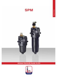
1 MDMMEDIUM PRESSURE INLINE FILTERP ressure FiltersMDM11 MPa (110 bar)Port sizes: 1/2 Flow rates: 8 75 l/minTECHNICAL DATAMax. working pressure: 11 MPa (110 bar)Max. testing pressure: 16 MPa (160 bar) Bursting pressure: 30 MPa (300 bar)Fatigue test: 0 9 MPa (90 bar) / cycles Working temperature: -25 C +110 CBypass valve: p 600 kPa (6 bar) 10%Filter element collapse pressure:standard: p 8 MPa (80 bar) except CD-CV series p 2 MPa (20 bar)Working temperature: -25 +110 CMATERIALHead and bowl: anodized aluminiumSeals: standard NBRon request FKMCOMPATIBILITY (ISO 2943)Full with fl uids: HH-HL-HM-HV-HTG (according to ISO 6743/4). For fl uids different than the above mentioned, please contact our Sales tests performed according to the following standards: ISO 2941: Element collapse resistance testISO 2942: Production integrity testISO 2943: Fluids compatibilityISO 3723: End load test methodISO 3724: Flow fatigue resistance methodISO 3968: Pressure drop versus fl ow rateISO 16889: Multipass test.
2 For further information contact our Technical FiltersMDMI ndicator 72on request only TypeType101102 MDMCDMF ilter mediaFilter mediaFTFCFDFVCDCVRDMVMSFTFCFDFVCDCVRDMVM SFT = 5 m(c) FC = 7 m(c)FD = 12 m(c)FV = 21 m(c)CD = 10 CV = 25 RD = 10 MV = 25 MS = 60 Inorganic fiber >1000 PaperFT = 5 m(c) FC = 7 m(c)FD = 12 m(c)FV = 21 m(c)CD = 10 CV = 25 RD = 10 MV = 25 MS = 60 Inorganic fiber >1000 PaperSealsSeals12121 = NBR Nitrile2 = FKM Fluoroelastomer1 = NBR Nitrile2 = FKM FluoroelastomerPortsB = BSPN = NPTS = SAEBNSBNSA ccessoriesXXXXXX = Not available XXBypass typeSCSCS = WithoutC = 600 kPa (6 bar)Port size333 = 1/2 Indicators035E6E7ET2035E6E7ET203 = Port, plugged5E = Visual differential 500 kPa (5 bar)6E = Electrical differential 500 kPa (5 bar)7E = 6E with LEDT2 = Electrical 500 kPa (5 bar) with thermostat 30 CSteel wire meshSteel wire mesh3 When the filter is ordered with FKM seals, the first digit of the indicator code is a letter (please see page 188-189).
3 HOW TO ORDER THE COMPLETE FILTERHOW TO ORDER THE FILTER ELEMENTP ressure FiltersMDME2E1D 1D2H6D 1H2H4H5H1H3RE36 556422 indicator PortTypeMDM 101 MDM 102 1/2 1/2 6,56,51572447878791662828505017176464767 67575606022220,650,85D1D2H1H2H3H4H5H6E1E 2E3 RWeightKgDIMENSIONAL LAYOUT(mm)Pressure FiltersMDMCLOGGING INDICATORS23164,5304835M20 x 1,5 NBRFKMD ifferential ELECTRICAL indicatorsRecommended tightening torque 90 NmSPDT differential switch. 14 - 30 V: > max resistive or inductive load 4 - 3 A 125-250 V: > max resistive or inductive load 1 A - Protection IP65 - Connector DIN 43650G R231+ ,5304835M20 x 1,5 NBRFKMR ecommended tightening torque 90 NmSPDT differential switch. 14 - 30 V: > max resistive or inductive load 4 - 3 A 125-250 V: > max resistive or inductive load 1 A - Protection IP65 - Connector DIN 43650 Differential ELECTRICAL indicators with LED (24 V) for visual indication705932M20 x 1,5O30 CNBRFKMR ecommended tightening torque 90 NmSPDT differential switch.
4 14 - 30 V: > max resistive or inductive load 4 - 3 A 125-250 V: > max resistive or inductive load 1 A - Protection IP65 - Connector DIN 43650 Differential ELECTRICAL indicators with THERMOSTAT 30 CO30 C704830M20 x 1,5 NBRFKMR ecommended tightening torque 90 NmSPDT differential switch. 14 - 30 V: > max resistive or inductive load 4 - 3 A 125-250 V: > max resistive or inductive load 1 A - Protection IP65 - Connector DIN 43650 Differential VISUAL ELECTRICAL indicators35,530 30M20 x 1,5 NBRFKM6 ESetting 500 kPa (5 bar)CE7 ESetting 500 kPa (5 bar)EET2 Setting 500 kPa (5 bar)DE72 Setting 500 kPa (5 bar)E25 ESetting 500 kPa (5 bar)AERecommended tightening torque 90 NmDifferential VISUAL indicatorsPressure FiltersMDMTypeCDM 101 CDM 1021,703,404,208,702,505,102,805,90 FTFVFCFDF ilter MediaTypeCDM 101 CDM 102 290600290600295600295600290600 RDMVCDCVMSF ilter MediaType pMDM 101 FTFCFDFVCDCVRDMVMS8122125283331353815223 54547525056602027455558656160 75 Filter MediaType pMDM 102 FTFCFDFVCDCVRDMVMS1014253840434546471725 44505358646668223052657075757575 Filter MediaTechnical data subject to variations without prior notice.
5 MDM 07/2013 FLOW RATES(l/min)DIRT HOLDING CAPACITY(g) ISO MTD p = 500 kPa (5 bar)FILTER AREA(cm2)The reference fluid has a kinematic viscosity of 30 cSt and a density of 0,86 different oil viscosity please contact our Sales Department for further kPa(0,5 bar)50 kPa(0,5 bar)100 kPa(1 bar)100 kPa(1 bar)150 kPa(1,5 bar)150 kPa(1,5 bar)Pressure FiltersMDM
