Transcription of RFC - SOFIMA HYD
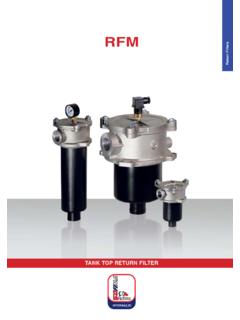
1 RFCTANK TOP RETURN FILTER, INSIDE TO OUTSIDE FILTRATION1 MPa (10 bar)RFC Port sizes: 3/4 2 1/2 Flow rates: 20 1000 l/minTECHNICAL DATAMax. working pressure: 1 MPa (10 bar)Max. testing pressure: 2 MPa (20 bar)Bursting pressure: 3 MPa (30 bar)Fatigue test: 0 500 kPa (5 bar) / cyclesBypass valve: p 170 kPa (1,7 bar) 0,2 Filter element collapse pressure: p 1 MPa (10 bar)Working temperature: -25 +110 CMATERIALSHead and cover: aluminiumBowl: steelElement support: size 100 - 200 polyamidesize 300 aluminiumDiffusor: zinc plated steelMagnetic core: syntherized magnetic materialSeals: standard NBR on request FKM COMPATIBILITY (ISO 2943)Full with fl uids: HH-HL-HM-HV-HTG (according to ISO 6743/4). For fl uids different than the above mentioned, please contact our Sales tests performed according to the following standards: ISO 2941: Element collapse resistance testISO 2942: Production integrity testISO 2943: Fluids compatibilityISO 3723: End load test methodISO 3724: Flow fatigue resistance methodISO 3968: Pressure drop versus fl ow rateISO 16889: Multipass test.
2 For further information contact our Technical size456--4 = 3/4 5 = 1 6 = 1 1/47 = 1 1/29 = 2 1/2456--456--456-----7----7----7-----9-- --9----9----9 PortsB = BSPN = NPTS = SAEF = SAE flange 3000 psiBNS-BNSF---FBNS-BNS-BNS-BNSFBNSF---F- --F---FBypass typeFF = 170 kPa (1,7 bar)FFFFFFFFFFS ealsSeals11 = NBR Nitrile 1 = NBR Nitrile 1111111111 TypeType CRCRFC110120130140220230240310320330340 Filter mediaFilter mediaFCFDFVCDRTMSFC = 7 m(c)FD = 12 m(c)FV = 21 m(c)CD = 10 RT = 30 MS = 60 FC = 7 m(c)FD = 12 m(c)FV = 21 m(c)CD = 10 RT = 30 MS = 60 Inorganic fiber >1000 Paper Inorganic fiber >1000 FCFDFVCDRTMSFCFDFVCDRTMSFCFDFVCDRTMSFCFD FVCDRTMSFCFDFVCDRTMSFCFDFVCDRTMSFCFDFVCD RTMSFCFDFVCDRTMSFCFDFVCDRTMSFCFDFVCDRTMS A ccessoriesSDS = Without D = With diffusor SDSDSDSDSDSDSDSDSDSDA ccessoriesSMS = WithoutM = With magnetic core SMSMSMSMSMSMSMSMSMSM11F03516171T1081191 Indicators0530P4-----05 = Port, plugged30 = Pressure gauge 0 600 kPa (6 bar)P4 = Pressure switch 03 = Port for differential indicator5B = Visual differential 130 kPa (1,3 bar) 6B = Electrical differential 130 kPa (1,3 bar)7B = 6B with LED T0 = Electrical 130 kPa (1,3 bar)
3 With thermostat 30 C0530P4-----0530P4-----0530P4-----0530P4 035B6B7BT00530P4035B6B7BT00530P4035B6B7B T00530P4035B6B7BT00530P4035B6B7BT00530P4 035B6B7BT00530P4035B6B7BT0 Indicator 70 on request onlydouble port on request onlyWhen the filter is ordered with FKM seals, the first digit of the indicator codeis a letter (please see page 188-189).Steel wire meshPaper Steel wire meshHOW TO ORDER THE COMPLETE FILTERHOW TO ORDER THE FILTER ELEMENTE3E4RH6H5H7H1H2H3D4D5H4E1E2D2D190 D7D6116D3D6D3 - without diffusorD8 - with diffusor Extra inlet on request for type 1/8 Differentialindicator PortTypeRFC 110 RFC 120 RFC 130 RFC 140 RFC 220 RFC 230 RFC 240 RFC 310 RFC 320 RFC 330 RFC 3408888888813113113116416416416490909090 134134134167167167167----M12M12M12M12M12 M12M127272727210610610612612612612689898 989133133133165,5165,5165,5165,512612612 6126175175175----70707089898989----10010 0100113113113113----35,735,735,750,850,8 50,850,868686868909090110110110110198198 2503502503205252903704705601061502003001 9026046521029039048014018523533522529550 0260340440530909090901291291291551551551 5538383838505050555555552828323236363655 5555556666121212141414142302753254453103 805803504305806201,21,41,51,74,24,75,08, 08,48,69.
4 1D1H1E1D2H2E2D3D8H3E3D4H4E4D5D6D7H5H6H7 RWeightKg1 1/2 SAE 30002 1/2 SAE 3000M8M8 M8M8M10M10M10M10-M12215 2203/4 - 1 -1 1/4 DIMENSIONAL LAYOUT(mm)CLOGGING INDICATORS64,5304835M20 x 1,5GR231+ 130 kPa (1,3 bar)NBRFKM7 BEBD ifferential ELECTRICAL indicator with LED (24V) for visual indicatorSPDT differential switch. 14 - 30 V: > max resistive or inductive load 4 - 3 A 125-250 V: > max resistive or inductive load 1 A - Protection IP65 - Connector DIN 43650 Recommended tightening torque 90 Nm705932M20 x 1,5O30 CSetting 130 kPa (1,3 bar)NBRFKMT0 DBDifferential ELECTRICAL indicator with THERMOSTAT 30 CSPDT differential switch. 14 - 30 V: > max resistive or inductive load 4 - 3 A 125-250 V: > max resistive or inductive load 1 A - Protection IP65 - Connector DIN 43650 Recommended tightening torque 90 Nm23164,5304835M20 x 1,5 Setting 130 kPa (1,3 bar)NBRFKM6 BCBD ifferential ELECTRICAL indicator SPDT differential switch.
5 14 - 30 V: > max resistive or inductive load 4 - 3 A 125-250 V: > max resistive or inductive load 1 A - Protection IP65 - Connector DIN 43650 Recommended tightening torque 90 Nm35,530 30M20 x 1,5 Setting 130 kPa (1,3 bar)NBRFKM5 BABD ifferential VISUAL indicator Recommended tightening torque 90 NmScale 0 600 kPa (600 bar)NBRFKM30-Pressure gauge 401/8 3011 Setting 130 kPa (1,3 bar)NBRFKMP4-Pressure switchATEX 3 GD EEx e T69771/8 24132 SPDT, 30V: > max resistive or inductive load 3A - 1A 125 or 250V: > max resistive or inductive load 3A - 0,5A respectivelyProtection IP65 - Connector DIN 43650 p = 30 40 kPa (0,3 0,4 bar) CRC 110 CRC 120 CRC 130 CRC 140 CRC 220 CRC 230 CRC 240 CRC 310 CRC 320 CRC 330 CRC 3404606508801320150020503670225031504250 5250460650880132015002050367022503150425 0525012501800245036004600640011800665092 001240015400 TypeFilter MediaRTMSCDCRC 110 CRC 120 CRC 130 CRC 140 CRC 220 CRC 230 CRC 240 CRC 310 CRC 320 CRC 330 CRC 3406,610,213,820,734,147,385,148,367,591 ,2112,37,3611,1014,9022,6037,3851,7092,9 052,6073,8099,60122,5010,916,522,233,555 ,376,5137,678,2109,2147,5181,7 TypeFilter MediaFCFDFVTypeRFC 110 RFC 120 RFC 130 RFC 140 RFC 220 RFC 230 RFC 240 RFC 310 RFC 320 RFC 330 RFC 3402035508080100160140120180250100125180 1501502003003003804806001251502502502504 0040050050085010003550651201201402401802 0031038011012520017017023030030039050060 01251502502502504004005005008501000 Filter MediaFCFVRTFDCDMST echnical data subject to variations without prior notice.
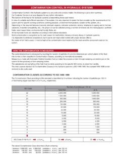
6 RFC 05/2017 FLOW RATES(l/min)DIRT HOLDING CAPACITY(g) ISO MTD p = 500 kPa (5 bar)FILTER AREA(cm2)The reference fluid has a kinematic viscosity of 30 cSt and a density of 0,86 different oil viscosity please contact our Sales Department for further information.