Transcription of SPM - SOFIMA HYDRAULIC FILTERS
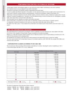
1 SPMMEDIUM PRESSURE INLINE FILTERP ressure FiltersSPM22 MPa (220 bar)Port sizes: 1/2 1 Flow rates: 10 130 l/minTECHNICAL DATAMax. working pressure: 22 MPa (220 bar)Max. test pressure: 33 MPa (330 bar)Bursting pressure: 66 MPa (660 bar)Fatigue test: 0 15 MPa (150 bar) / cycles Bypass valve: p 350 kPa (3,5 bar) 10% p 600 kPa (6 bar) 10%Filter element collapse pressure: standard: p 2,1 MPa (21 bar)Working temperature: -25 +110 CMATERIALSHead and bowl: anodized aluminiumSeals: standard NBRon request FKMCOMPATIBILITY (ISO 2943)Full with fl uids: HH-HL-HM-HV-HTG (according to ISO 6743/4).
2 For fl uids different than the above mentioned, please contact our Sales tests performed according to the following standards: ISO 2941: Element collapse resistance testISO 2942: Production integrity testISO 2943: Fluids compatibilityISO 3723: End load test methodISO 3724: Flow fatigue resistance methodISO 3968: Pressure drop versus fl ow rateISO 16889: Multipass test. For further information contact our Technical FiltersSPMXX = Not available 03 = Port, plugged5D = Visual differential 250 kPa (2,5 bar) 5E = Visual differential 500 kPa (5 bar)6D = Electrical differential 250 kPa (2,5 bar)6E = Electrical differential 500 kPa (5 bar)7D = 6D with LED7E = 6E with LED T6 = Electrical 250 kPa (2,5 bar) with thermostat 30 C T2 = Electrical 500 kPa (5 bar)
3 With thermostat 30 CIndicator 72 - 76on request only 1 = NBR Nitrile2 = FKM Fluoroelastomer1 = NBR Nitrile2 = FKM FluoroelastomerTypeType301302 SPMCCHF ilter mediaFilter mediaFTFCFDFVCDCVRDMVFTFCFDFVCDCVRDMVFT = 5 m(c)FC = 7 m(c)FD = 12 m(c)FV = 21 m(c)CD = 10 CV = 25 RD = 10 MV = 25 FT = 5 m(c)FC = 7 m(c)FD = 12 m(c)FV = 21 m(c)CD = 10 CV = 25 RD = 10 RV = 25 SealsSeals1212 PortsB = BSPN = NPTS = SAEBNSBNSPort size3453453 = 1/2 (NPT not available) 4 = 3/4 5 = 1 AccessoriesXXXXXXB ypass typeSDCSDCS = Whitout D = 350 kPa (3,5 bar)C = 600 kPa (6 bar)Indicators035D5E6D6E7D7ET6T2035D5E6D 6E7D7ET6T2 Inorganic fiber >1000 PaperSteel wire meshInorganic fiber >1000 PaperSteel wire meshWhen the filter is ordered with FKM seals, the first digit of the indicator code is a letter (please see page 188-189).
4 HOW TO ORDER THE COMPLETE FILTERHOW TO ORDER THE FILTER ELEMENTP ressure ,5 Indicator PortTypeSPM 301 SPM 3022052981111971,72,21/2 - 3/4 - 1 D1H1H2 Weight KgDIMENSIONAL LAYOUT(mm)Pressure FiltersSPMCLOGGING INDICATORS23164,5304835M20 x 1,5 NBRFKMD ifferential ELECTRICAL indicators6 DSetting 250 kPa (2,5 bar)CD6 ESetting 500 kPa (5 bar)CERecommended tightening torque 90 NmSPDT differential switch. 14 - 30 V: > max resistive or inductive load 4 - 3 A 125-250 V: > max resistive or inductive load 1 A - Protection IP65 - Connector DIN 43650GR231+ ,5304835M20 x 1,5 NBRFKM7 DSetting 250 kPa (2,5 bar)ED7 ESetting 500 kPa (5 bar)EERecommended tightening torque 90 NmSPDT differential switch.
5 14 - 30 V: > max resistive or inductive load 4 - 3 A 125-250 V: > max resistive or inductive load 1 A - Protection IP65 - Connector DIN 43650 Differential ELECTRICAL indicators with LED (24 V) for visual indication705932M20 x 1,5O30 CNBRFKMT2 Setting 250 kPa (2,5 bar)Setting 250 kPa (2,5 bar)DESetting 500 kPa (5 bar)Recommended tightening torque 90 NmSPDT differential switch. 14 - 30 V: > max resistive or inductive load 4 - 3 A 125-250 V: > max resistive or inductive load 1 A - Protection IP65 - Connector DIN 43650 Differential ELECTRICAL indicators with THERMOSTAT 30 CO30 C704830M20 x 1,5 NBRFKM72 Setting 500 kPa (5 bar)E2 Recommended tightening torque 90 NmSPDT differential switch.
6 14 - 30 V: > max resistive or inductive load 4 - 3 A 125-250 V: > max resistive or inductive load 1 A - Protection IP65 - Connector DIN 43650 Differential VISUAL ELECTRICAL indicators35,530 30M20 x 1,5 NBRFKM5 DSetting 250 kPa (2,5 bar)AD5 ESetting 500 kPa (5 bar)AERecommended tightening torque 90 NmDifferential VISUAL indicatorsT676 DDE6 Pressure FiltersSPMType pSPM 301 FTFCFDFVCDCVRDMV252739628011010011255627 3110130130130130708195130130130130130 Filter MediaType pSPM 302 FTFCFDFVCDCVRDMV343850751221301301306373 841191301301301307990104130130130130130 Filter MediaTypeCCH 301 CCH 3025,19,410,919,66,712,67,414.
7 0 FTFVFCFDF ilter Media975178577014559751785 CVMVCDTypeCCH 301 CCH 3027701455 RDFilter MediaTechnical data subject to variations without prior notice. SPM 07/2013 FLOW RATES(l/min)DIRT HOLDING CAPACITY(g) ISO MTD p = 500 kPa (5 bar)FILTER AREA(cm2)The reference fluid has a kinematic viscosity of 30 cSt and a density of 0,86 different oil viscosity please contact our Sales Department for further kPa(0,5 bar)50 kPa(0,5 bar)150 kPa(1,5 bar)150 kPa(1,5 bar)100 kPa(1 bar)100 kPa(1 bar)Pressure FiltersSPM