Transcription of Measuring Self Resonant Frequency
1 Measuring self Resonant FrequencyDocument 363-1 Specifications subject to change without notice. Document 363-1 Revised 09/16/03 IntroductionWhen comparing published electrical values, engineersrequire a common basis for comparison. Ideally, a 100 nHinductor with a self Resonant Frequency (SRF) of 1 GHzfrom one manufacturer is equivalent to inductors with thesame published values from every other , however, the test instrument and fixture af-fect the SRF measurement. Since all manufacturers donot use the same instruments and fixtures, not all pub-lished SRF specifications are equivalent, which makesinductor comparisons difficult. The following discussion isintended to provide insight into practical SRF determina-tions and Resonance of InductorsIdeal inductors would have zero resistance and zero ca-pacitance. But, real inductors have parasitic resistanceand capacitance.
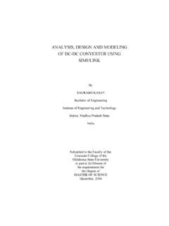
2 The first self Resonant Frequency of aninductor is the lowest Frequency at which an inductor reso-nates with its self -capacitance. The first resonance can bemodeled by a parallel combination of inductance and ca-pacitance, shown in Figure 1. Resistor R1 limits imped-ance near the Resonant the SRF of an inductor, all of the following conditions aremet: The input impedance is at its peak. The phase angle of the input impedance is zero, cross-ing from positive (inductive) to negative (capacitive). Since the phase angle is zero, the Q is zero. The effective inductance is zero, since the negative ca-pacitive reactance (Xc = 1 / j C) just cancels the posi-tive inductive reactance (XL = j L). The 2-port insertion loss ( S21 dB) is a maximum,which corresponds to the minimum in the plot of fre-quency vs. S21 dB. The 2-port phase ( S21) angle is zero, crossing fromnegative at lower frequencies to positive at higher measurement of any of these conditions can be used todetermine the SRF of an Capacitance Affects SRFH istorically, inductor capacitance is called inter-windingcapacitance based on the assumption that it is the resultof charge separation between insulated coil , if the inductor is measured over a conductingground plane, capacitance between the coil and the groundplane is also part of the measurement.
3 The distance of thecoil from the measurement ground plane and the effectivedielectric constant of the measurement substrate affectsthe capacitance to ground. This partially explains how thetest fixture affects the SRF measurement. The followingequation shows how the SRF is related to inductance andcapacitance in an LC =in Hz2(LC) where :L is the inductance in HenriesC is the capacitance in FaradsFrom this equation, it is clear that increasing inductance orcapacitance lowers the measured SRF. Reducing induc-tance or capacitance raises the Effects on SRF MeasurementsA fixture is required to connect an inductor to the terminalsof a test instrument. After calibration and fixture compensa-tion are performed, it is assumed that all fixture effects havebeen de-embedded (removed) from the compensation uses open and short standards, butit cannot predict the interaction of a specific inductor withthe test fixture.
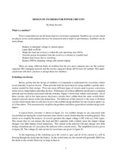
4 Therefore, some residual capacitance be-tween the measured inductor and the fixture may existafter calibration and fixture compensation. The result isthat SRF measurements of the same inductor can changewith each different combination of instrument and states the specific instrument and fixture used tomeasure the SRF of its illustrate the effect of residual fixture capacitance onSRF, Figure 2 plots the effective series inductance of a100 nH chip inductor using AWR Microwave Office / VisualSystem Simulator 2002. The modified SPICE model simu-lation shows the effect of an additional pF of capaci-tance to ground at the input terminal. The term effectiveinductance is used, because the low- Frequency induc-tance is the same (100 nH) for both models, but the induc-Figure 1. Inductor ModelCR1R2 LRVARRVARRVARRVARD ocument 363-2 Specifications subject to change without notice. Document 363-2 Revised 09/16/03tance near the SRF is affected by capacitance betweenthe inductor and the effect of residual fixture capacitance is more pronouncedon lower value inductors.
5 The effect of residual fixture ca-pacitance on larger power inductors is often important conclusions can be made from Figure 2: A slight difference in fixture design and calibration canhave a large effect on the measured SRF. In the region of the measured SRF, a small difference infixture design and calibration can mean the differencebetween reading a large positive inductance or a largenegative capacitance. If the parasitic capacitance (and inductance) of the cir-cuit board to which an inductor is attached is differentfrom the test fixture, the SRF measurement of the board-mounted inductor will be different. Since SRF measurements are fixture/substrate-depen-dent, a typical SRF cannot be defined when the fixtureeffect is Small Differences in Capacitance Affect QFigure 3 illustrates the effect of residual fixture capaci-tance on Q values. The values represent the Q for theoriginal inductor model plotted in Figure 2 compared to theQ of the same inductor with an additional pF of ca-pacitance to ground at the input terminal.
6 At lower frequen-cies, the residual fixture capacitance has little effect on theQ value. At higher frequencies, the effect on Q becomessignificant. In this example, the small residual capacitanceto ground causes the peak Q value to shift by 132 MHzand to decrease in magnitude by 23% of the original Coilcraft Measures Inductor SRFWhen compiling data for publication, Coilcraft normallyuses the same instrument and fixture to measure the SRFof all our chip inductors and power inductors: an Agilent/HP Vector Network Analyzer and a Coilcraft SMD-D (2-port) test fixture. The SRF is determined to be the fre-quency at which the insertion (S21) phase changes fromnegative through zero to SRF measurements are so sensitive to fixtureeffects, we specify the SRF for our low inductance RF chipinductors as a minimum value, approximately 15% to20% below the actual average measurement of a repre-sentative sample.
7 Since fixture effects become negligiblefor higher inductance values, SRF for our power inductorsis specified as typical. Comparing Coilcraft Inductor SRF to OtherInductorsWhen comparing the SRF of Coilcraft chip inductors toother inductors, the same instrument, fixture, calibration,and fixture compensation standards should be used. Ifnot, any differences in SRF specifications may be maskedby instrument and fixture effects, possibly causing incor-rect 2. Effective Inductance With Residual Capacitance Effects150 MHz100 nH150 MHz100 nH1694 MHz0 nH1606 MHz0 nH3000200010000 100020003000 0500100015002000 Frequency (MHz)Inductance (nH)Effective inductanceL_SRL (nH)Modified SPICE modelL_SRL (nH)original SPICE modelSimulating Substrate-Dependent SRFR emeasuring the SRF of inductors for each new applica-tion circuit board is clearly not convenient or timely for cir-cuit designers. There is an easier way to determine the SRFof an inductor in a specific application: circuit the best extent possible, fixture effects are removedfrom our measurements before we create our SPICE mod-els and S-parameters.
8 As a result, the SRF of the de-embedded measurement is higher than the yet, the de-embedded SRF is not the true SRF. Thetrue SRF of any inductor always depends on the specificcharacteristics of the circuit board to which it is other words, the SRF is simulating the Coilcraft model over a specific circuitboard substrate, you can determine the SRF of an induc-tor for your application. The circuit board substrate dielec-Figure 3. Effect of Capacitance on Measured Q|Eqn| Q modified|Eqn| Q original90807060504030201000500100015002 000 Frequency (MHz)150 MHz39654 MHz75522 MHz58150 MHz381694 MHz01606 MHz0Q of inductorQ Factortric constant and thickness, and the size and layout of theconductor traces in the vicinity of the inductor determinethe SRF of the s RF and microwave design software offers high-accuracy libraries of many of our chip inductor models are substrate-scalable, based on measure-ments of our inductors over various thicknesses of FR4and applying the circuit board characteristics and tolerancesto the simulation, circuit designers can see the effects theyhave on the SRF and all other electrical characteristics,such as inductance, Q, input impedance, phase, insertionloss and return loss.
9 This knowledge gives the designer apractical basis to apply when comparing inductors, andultimately can answer the question of whether an inductoris appropriate for the 363-3 Specifications subject to change without notice. Document 363-3 Revised 09/16/03