Transcription of MELSEC iQ-F FX5-4AD-ADP Hardware Manual
1 This Manual confers no industrial property rights or any rights of any other kind, nor does it confer any patent licenses. mitsubishi electric Corporation cannot be held responsible for any problems involving industrial property rights which may occur as a result of using the contents noted in this of loss in opportunity and secondary loss from warranty liabilityRegardless of the gratis warranty term, mitsubishi shall not be liable for compensation to:(1) Damages caused by any cause found not to be the responsibility of mitsubishi .(2) Loss in opportunity, lost profits incurred to the user by Failures of mitsubishi products.(3) Special damages and secondary damages whether foreseeable or not, compensation for accidents, and compensation for damages to products other than mitsubishi products.
2 (4) Replacement by the user, maintenance of on-site equipment, start-up test run and other safe useThis product has been manufactured as a general-purpose part for general industries, and has not been designed or manufactured to be incorporated in a device or system used in purposes related to human using the product for special purposes such as nuclear power, electric power, aerospace, medicine or passenger movement vehicles, consult with mitsubishi product has been manufactured under strict quality control. However when installing the product where major accidents or losses could occur if the product fails, install appropriate backup or failsafe functions in the system. HEAD OFFICE : TOKYO BUILDING, 2-7-3 MARUNOUCHI, CHIYODA-KU, TOKYO 100-8310, JAPANSideASideBJAPANESEENGLISHJY997D6020 1 ESideBSafety Precautions (Read these precautions before use.)
3 This Manual classifies the safety precautions into two categories: and .Depending on the circumstances, procedures indicated by may alsocause severe is important to follow all precautions for personal ManualsHow to obtain manualsFor the necessary product manuals or documents, consult with your localMitsubishi electric that incorrect handling may cause hazardousconditions, resulting in death or severe that incorrect handling may cause hazardousconditions, resulting in minor or moderate injury orproperty nameManual iQ-F FX5U User's Manual ( Hardware )JY997D55301 Explains FX5U PLC specification details for I/O,wiring, installation, iQ-F FX5UC User's Manual ( Hardware )JY997D61301 Explains FX5UC PLC specification details for I/O,wiring, installation, iQ-F FX5 User's Manual (Analog Control - CPU modulebuilt-in, Expansion adapter)JY997D60501 Describes the analog function of the CPU module built-in and the analog standardsFX5-4AD-ADP comply with the EC Directive (EMC Directive) and UL standards (UL,cUL).
4 Further information can be found in the following Manual . MELSEC iQ-F FX5U User's Manual ( Hardware ) MELSEC iQ-F FX5UC User's Manual ( Hardware )Regarding the standards that relate to the CPU module, please refer to either theproduct catalog or consult with your nearest mitsubishi product product is designed for use in industrial for EC Directive Installation in EnclosureProgrammable controllers are open-type devices that must be installed and usedwithin conductive control cabinets. Please use the programmable controller whileinstalled within a conductive shielded control cabinet. Installation within a controlcabinet greatly affects the safety of the system and aids in shielding noise from theprogrammable controller. Control cabinet- The control cabinet must be Ground the control cabinet with the thickest possible grounding To ensure that there is electric contact between the control cabinet and its door, connect the cabinet and its doors with thick wires.
5 - In order to suppress the leakage of radio waves, the control cabinet structure must have minimal openings. Also, wrap the cable holes with a shielding cover or other shielding The gap between the control cabinet and its door must be as small as possible by attaching EMI gaskets between them.*1 These wires are used to improve the conductivity between the door and controlcabinet. Cables- Make sure to use shielded cables as cables pulled out of the control Connect the shield such as shielded cables and shielding covers to the grounded control cabinet. It is possible that the accuracy temporarily fluctuates within 10 %. Set the number of times of winding to "2 turns" within approximately 200 mm fromthe terminal block of the analog cable on the FX5-4AD-ADP side, and attach aferrite core.
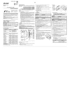
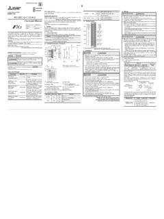
6 (Ferrite core used in our test: E04SR401938 manufactured by SEIWAELECTRIC MFG. CO., LTD.)1. OutlineThe FX5-4AD-ADP expansion adapter for analog input (hereinafter called 4AD-ADP) isa expansion adapter to add four analog input Incorporated ItemsVerify that the following product and items are included in the package:ProductFX5-4AD-ADP analog input expansion adapterIncluded ItemsHardware Manual (This Manual )Shielding coverShielded cableWires*1 EMI External Dimensions, Part Names, and Terminal Layout2. InstallationFor the installation, refer to the following Manual . MELSEC iQ-F FX5U User's Manual ( Hardware ) MELSEC iQ-F FX5UC User's Manual ( Hardware )[1] DIN rail mounting groove (DIN rail: DIN46277, 35 mm wide)[2] Name plate[3] Expansion adapter slide lock[4] Expansion adapter connector cover[5] Direct mounting hole: 2 holes of (mounting screw: M4 screw)[6] PWR LED (green)[7] Terminal block (European type terminal block)[8] Expansion adapter connector[9] DIN rail mounting hook[10] Expansion adapter fixing hook[11] Expansion adapter connectorINSTALLATION PRECAUTIONS Make sure to cut off all phases of the power supply externally before attemptinginstallation or wiring to do so may cause electric shock or damage to the product.
7 Use the product within the generic environment specifications described in theUser's Manual ( Hardware ) of the CPU module use the product in areas with excessive dust, oily smoke, conductive dusts,corrosive gas (salt air, Cl2, H2S, SO2 or NO2), flammable gas, vibration orimpacts, or expose it to high temperature, condensation, or rain and the product is used in such conditions, electric shock, fire, malfunctions,deterioration or damage may PRECAUTIONS Do not touch the conductive parts of the product directly. Doing so may cause device failures or malfunctions. When drilling screw holes or wiring, make sure that cutting and wiring debris donot enter the ventilation slits of the to do so may cause fire, equipment failures or malfunctions.
8 Install the product on a flat the mounting surface is rough, undue force will be applied to the PC board,thereby causing nonconformities. Install the product securely using a DIN rail or mounting screws. Connect the expansion board and expansion adapter securely to their connections may cause (mounting hole pitch) [6][5][10]Unit: mmTerminallayout[7][8][9][3][2][4][1]V1+ I1+COM1V3+I3+V2+I2+V4+I4+COM4 COM3 COM2 Weight: Approx. kgOuter painting color: Munsell adapter connector cover is removed[11]3. Cable end treatment and tightening type terminal block1) Suitable wiring2) Tightening torqueTighten the terminal screws with N not tighten the screws outside the specified to do so may cause equipment failures or ) Wire end treatmentStrip the coating of strand wire and twist the cable core before connecting it,or strip the coating of single wire before connecting using a wire ferrule with an insulating sleeve, choose a wire withproper cable sheath referring to the above outside dimensions, otherwisethe wire cannot be inserted easily.
9 <Reference>WIRING PRECAUTIONS Make sure to cut off all phases of the power supply externally beforeattempting installation or wiring to do so may cause electric shock or damage to the product. Make sure to properly wire to the terminal block (European type) inaccordance with the following to do so may cause electric shock, equipment failures, a short-circuit,wire breakage, malfunctions, or damage to the The disposal size of the cable end should follow the dimensions described in the Tightening torque should follow the specifications in the Twist the ends of stranded wires and make sure that there are no loose Do not solder-plate the electric wire Do not connect more than the specified number of wires or electric wires of unspecified Affix the electric wires so that neither the terminal block nor the connected parts are directly PRECAUTIONS When drilling screw holes or wiring.
10 Make sure that cutting and wiring debrisdo not enter the ventilation slits of the to do so may cause fire, equipment failures or malfunctions. Make sure to observe the following precautions in order to prevent anydamage to the machinery or accidents due to malfunction of the PLC causedby abnormal data written to the PLC due to the effects of noise:1) Do not bundle the power line or analog input/output cable together with orlay them close to the main circuit, high-voltage line, load line or powerline. As a guideline, lay the power line, control line and communicationcables at least 100 mm away from the main circuit, high-voltage line, loadline or power ) Ground the shield of the analog input/output cable at one point on thesignal receiving side.