Transcription of Merlin Gerin Circuit breaker application guide
1 Merlin GerinCircuit breakerapplication guideMMMMMMMMMMMMMMERLIN Gerin multi 9C60NC63400Va6000242342410kA IEC - OFFO - OFFO - OFFO - OFF681357 Merlin Gerin multi 9C60NC25230Va600024178O - OFF10 kA IEC Gerin multi 9C60NC63400Va6000242342410kA IEC - OFFO - OFFO - OFFO - 22 SE90105%IralarmImIrIn=250A250NP93083 OFFMERLIN Gerin compactNS250 NUi 750V. Uimp AIEC947-2 UTE VDE BS CEI UNE NEMAUe(V)Icu(kA)Ics=100% Icu160 22 SE90105%IralarmImIrIn=250 AOFFMERLIN Gerin compactNS250 NUi 750V. Uimp AIEC947-2 UTE VDE BS CEI UNE NEMAUe(V)Icu(kA)Ics=100% Icu160/250 ApushtotrippushtotripMERLINGERIN multi 9ID'clicC3240 mA n 0,030A230Va2056420564ID'clicbi 40 ABS EN 61009a30003N1L13L2I.
2 ONMERLIN Gerin multi 9NG 125 LIn = 125A220/240V380/415V440V500 VUe(V)5025156 IEC (kA) 22 SE90105%IralarmImIrIn=250A250NP93083 OFFMERLIN Gerin compactNS250 NUi 750V. Uimp AIEC947-2 UTE VDE BS CEI UNE NEMAUe(V)Icu(kA)Ics=100% Icu160/250 ApushtotrippushtotripIc P>Ir>ImtestfaultSTR 53 UE607590105 %IrIImIrIotrtm(s)x Inx Irx Iox Inon I2t off(s) at IrtestRtrtmImIrIMERLIN Gerin compactNS400 HUi (V)220/240380/415440500/525660/690100706 54035 IEC 947-2 UTE VDE BS CEIUNE NEMAIcu(kA)cat BIcs = 100% IcuIcw 6kA / 0,25sIn = 22 SE90105%IralarmImIrIn=250 AOFFMERLIN Gerin compactNS250 NUi 750V. Uimp AIEC947-2 UTE VDE BS CEI UNE NEMAUe(V)Icu(kA)Ics=100% Icu160/250 ApushtotrippushtotripResetresetApIgI nIsdI iIrMicrologic 70 Ics = 100% Icu220/44052569010010085 Icw85kA/1sNX 32 H 947-2 UTEVDEBSCEIUNEASNEMAEN 60947-250/60 HzUeIcu(V)(kA)
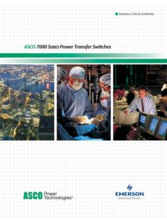
3 01253push OFFpush ONO OFFdischarged1 ContentsDescriptionCircuit breakers and system designThe requirements for electrical power distributionSafety and availability of energyStructure of LV electrical power distributionFunctions and technologies of protection devicesStandard BS EN 60947-2 current limitationCascadingDiscriminationEarth leakage protection discriminationRange of Circuit breakersDiscrimination rulesLV discrimination studyEnhanced discrimination and cascadingSupplementary requirementsTransformer informationCable fault reduction400Hz operationDC informationResidual current device selectionCircuit breaker markingsLV switch disconnectorsTechnical dataCascading tablesDiscrimination tablesType 2 co-ordinationtables for motor protectionCo-ordination with Telemecanique busbarSection123 Page3557721000 kVA1000 AMM100 A400 A100 A160 A75 kW16 A20 kV/400 V1000 kVA1600 A1000 kVA19 kA45 kA60 kA23 kA70 kAmainswitchboardbuilding utilitieslighting, heating.
4 Distributionswitchboard -industrial/commercialnon-priorityfeeder spriority feedersdistributiondistributionenclosure distributionworkshop 13 Section 1 System requirementsCircuit breakers and system designSafety and availability of energyStructure of LV electrical power distributionFunctions and technologies of protection devicesStandard BS EN 60947-2 current limitationCascadingDiscriminationDiscrim ination rulesEarth leakage protection discriminationCoordination of protection devicesRange of Circuit breakersLV discrimination studyEnhanced discrimination and cascadingPage567101519212526283043464 GlossaryEDW:SCPD:IEC:BS:CT:CU:MSB:BBT:MV :Isc:Isc(D1):Usc:MCCB:BC:Icu(*):IcuD1(*) Ue:Ui:Uimp:In:Ith:Ithe:Iu:Icm:Icu:Ics:Ic w: x x Ir:Ii:Isd.
5 ElectroDynamic WithstandShort Circuit protection deviceInternational Electrotechnical CommissionBritish StandardCurrent transformerscontrol UnitMain SwitchboardBusbar TrunkingMedium Voltage (1kV to 36kV)Short- Circuit currentShort- Circuit current at the point D1 is installedShort- Circuit voltageMoulded case Circuit -breakerBreaking CapacityUltimate Breaking CapacityUltimate Breaking Capacity of D1 Rated operational voltageRated insulation voltageRated impulse withstand voltageRated operational currentConventional free air thermal currentConventional enclosed thermal currentRated uninterrupted currentRated short- Circuit making capacityRated ultimate short- Circuit breaking capacityRated service breaking capacityRated short time withstand currentAdjustable overload setting currentConventional non-tripping
6 CurrentConventional tripping currentInstantaneous tripping setting currentShort time tripping setting current5 The design of LV installations leads to basic protection devicesbeing fitted for three types of faults:c overloadsc short-circuitsc insulation of these protection devices must allow for:c the statutory aspects, particularly relating to safety of people,c technical and economic chosen switchgear must:c withstand and eliminate faults at optimised cost with respect to the necessaryperformance,c limit the effect of a fault to the smallest part possible of the installation in order toensure continuity of of these objectives requires coordination of protection deviceperformance, necessary for:c managing safety and increasing durability of the installation by limiting stresses,c managing availability by eliminating the fault by means of the Circuit -breakerimmediately upstreamThe Circuit - breaker coordination means are.
7 C cascadingc the insulation fault is specifically dealt with by earth fault protection devices,discrimination of the residual current devices (RCDs) must also be and availability of energyare the operator s of protection devicesensures these needs are met atoptimised and availability of energyThe requirements of electrical power distribution6 The various levels of an LV electrical installationEach of the three levels of the installation has specific availability and safety of LV electrical powerdistributionThe requirements of electrical power distributionSimplified diagram of a standard installation covering most of the cases observed in kVA1000 AMM100 A400 A100 A160 A75 kW16 A20 kV/400 V1000 kVA1600 A1000 kVA19 kA45 kA60 kA23 kA70
8 KAmainswitchboardbuilding utilitieslighting, heating, distributionswitchboard -industrial/commercialnon-priorityfeeder spriority feedersdistributiondistributionenclosure distributionworkshop 1 Level ALevel BLevel C7 Circuit - breaker functionsThis connection device is able to close and break a Circuit regardless of current up toits breaking functions to be performed are:c close the Circuit ,c conduct current ,c open the Circuit and break the current ,c guarantee requirements concerning installation, cost optimisation, management ofavailability and safety generate technological choices concerning the A: the Main Switchboard (MSB)This unit is the key to the entire electrical power distribution : availability of supply isessential in this part of the Short- Circuit currents are high due to.
9 V the proximity of the LV sources,v amply sized busbars for conveying high This is the area of the power Circuit -breakersFunctions and technologies of theprotection devicesOwn current compensationdiagramProtection devices and theircoordination must be suited tothe specific features of At the main switchboard, the needfor energy availability is greatest,c At the sub-distributionswitchboards, limitation of stressesin event of a fault is important,c At final distribution , user safety Main data of these Circuit -breakers:v of industrial type, meeting standard BSEN 60947-2,v with a high breaking capacity lcu from 40 to 150 kA,v with a nominal rating of 1000 to more than 5000 A,v category B:- with a high lcw from 40 kA to 100 kA 1 s- with a high electrodynamic withstand (EDW),v with a stored energy operating mechanism allowing source of supply is ensured by total discrimination:v upstream with the protection fuses of the HV/LV transformer (*),v downstream with all the feeders (time discrimination).
10 (*) The value of HV/LV discrimination lies above all in the fact that resumption of operation hasfewer constraints in LV (accessibility, padlocking). This offers considerable advantages forcontinuity of Circuit -breakers are designed for high currentelectrical distribution :v they are normally installed in the MSBs to protecthigh current incomers and feeders;v they must remain closed in event of short-circuits soas to let the downstream Circuit - breaker eliminate thefaults. Their operation is normally Withstand (EDW) and high thermalwithstand characterised by a short time withstandcurrent lcw are is designed to be as great as possible by an owncurrent compensation B: the subdistribution boardsThese boards belong to the intermediate part of the installation:c distribution is via conductors (BBT or cables) with optimised sizing,c sources are still relatively close.