Transcription of MicroLogix 1100 Programmable Controllers - Rockwell …
1 Installation InstructionsMicroLogix 1100 Programmable ControllersCatalog Numbers 1763-L16 AWA, 1763-L16 BWA, 1763-L16 BBB, 1763-L16 DWDTo p i cP a g eImportant User Information4 Additional Resources5 Overview6 Controller Description7 Hazardous Location Considerations8 Mounting the Controller10 Connecting 1762 I/O Expansion Modules16 Wiring the Controller17 Specifications234 Publication 1763-IN001C-EN-P - June 2015 Important User InformationSolid state equipment has operational characteristics differing from those of electromechanical equipment. Safety Guidelines for the Application, Installation and Maintenance of Solid State Controls (Publication available from your local Rockwell Automation sales office or online at ) describes some important differences between solid state equipment and hard-wired electromechanical devices.
2 Because of this difference, and also because of the wide variety of uses for solid state equipment, all persons responsible for applying this equipment must satisfy themselves that each intended application of this equipment is no event will Rockwell Automation, Inc. be responsible or liable for indirect or consequential damages resulting from the use or application of this examples and diagrams in this manual are included solely for illustrative purposes. Because of the many variables and requirements associated with any particular installation, Rockwell Automation, Inc. cannot assume responsibility or liability for actual use based on the examples and patent liability is assumed by Rockwell Automation, Inc.
3 With respect to use of information, circuits, equipment, or software described in this of the contents of this manual, in whole or in part, without written permission of Rockwell Automation, Inc., is this manual, when necessary, we use notes to make you aware of safety information about practices or circumstances that can cause an explosion in a hazardous environment, which may lead to personal injury or death, property damage, or economic information that is critical for successful application and understanding of the information about practices or circumstances that can lead to personal injury or death, property damage, or economic loss. Attentions help you identify a hazard, avoid a hazard and recognize the HAZARDL abels may be on or inside the equipment (for example, drive or motor) to alert people that dangerous voltage may be HAZARDL abels may be on or inside the equipment (for example, drive or motor) to alert people that surfaces may reach dangerous temperatures.
4 5 Publication 1763-IN001C-EN-P - June 2015 Additional ResourcesIf you would like a manual, you can: download a free electronic version from the internet: purchase a printed manual by contacting your local Allen-Bradley distributor or Rockwell Automation representativeResourceDescriptionMicroLo gix 1100 Programmable Controllers User Manual 1763-UM001A more detailed description of how to install and use your MicroLogix 1100 Programmable controller and expansion I/O 1100 Instruction Set Reference Manual1763-RM001A reference manual that contains data and function files, instruction set, and troubleshooting information for MicroLogix Instructions 1762-INxxxInformation on installing and using 1762 expansion I/O Automation Wiring and Grounding Guidelines information on proper wiring and grounding Publication 1763-IN001C-EN-P - June 2015 OverviewMicroLogix 1100 Controllers are suitable for use in an industrial environment when installed in accordance with these instructions.
5 Specifically, this equipment is intended for use in clean, dry environments (Pollution degree 2(1)) and with circuits not exceeding Over Voltage Category II(2) (IEC 60664-1).(3)Install your controller using these installation instructions.(1)Pollution Degree 2 is an environment where, normally, only non-conductive pollution occurs except that occasionally a temporary conductivity caused by condensation shall be expected.(2)Over Voltage Category II is the load level section of the electrical distribution system. At this level transient voltages are controlled and do not exceed the impulse voltage capability of the product s insulation.(3)Pollution Degree 2 and Over Voltage Category II are International Electrotechnical Commission (IEC) not remove the protective debris strip until after the controller and all other equipment in the panel near the controller are mounted and wiring is complete.
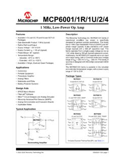
6 Once wiring is complete, remove protective debris strip. Failure to remove strip before operating can cause discharge can damage semiconductor devices inside the controller. Do not touch the connector pins or other sensitive strip 7 Publication 1763-IN001C-EN-P - June 2015 Controller DescriptionItemDescription1 output Terminal Block2 Battery Connector3 Bus Connector Interface to Expansion I/O4 Battery5 input Terminal Block6 LCD Display7 LCD Display Keypad (ESC, OK, Up, Down, Left, Right)8 Status LEDs9 Memory Module Port Cover(1) -or- Memory Module(2)(1)Shipped with controller.(2)Optional rail Latches11RS-232/485 Communication Port (Channel 0, isolated)12 Ethernet Port (Channel 1)121112356789104 ESCOK8 Publication 1763-IN001C-EN-P - June 2015 Hazardous Location ConsiderationsThis equipment is suitable for use in Class I, Division 2, Groups A, B, C, D or non-hazardous locations only.
7 The following WARNING statement applies to use in hazardous NumberDescriptionInput PowerDigital InputsAnalog InputsDigital OutputsComm. Ports1763-L16 AWA120/240V ac(10) 120V ac(2) voltage dc(6) relayAll individually isolated(1) RS-232/485 combo (isolated)(1) Ethernet1763-L16 BWA120/240V ac(6) 24V dc(4) high-speed 24V dc(1)(1)The 4 high-speed inputs (inputs 0 through 3) can be used for pulse latching or higher speed counting. Refer to input Specifications on page 25 and the MicroLogix 1100 Instruction Set Reference Manual, publication 1763-RM001, for more information.(2) voltage input0 ..10V dc(6) relayAll individually isolated(1) RS-232/485 combo (isolated)(1) Ethernet1763-L16 BBB24V dc(6) 24V dc(4) high-speed 24V dc(1)(2) voltage dc(2) relay (isolated)(2) 24V dc FET(2) high-speed 24V dc FET(1) RS-232/485 combo (isolated)(1) Ethernet1763-L16 DWD12/24V dc(6) 12/24V dc(4) high-speed 12/24V dc(1)(2) voltage dc(6) relayAll individually isolated(1) RS-232/485 combo (isolated)(1) Ethernet 9 Publication 1763-IN001C-EN-P - June 2015 WARNINGEXPLOSION HAZARD Substitution of components may impair suitability for Class I, Division 2.
8 Do not replace components or disconnect equipment unless power has been switched off. Do not connect or disconnect components unless power has been switched off. This product must be installed in an enclosure. All cables connected to the product must remain in the enclosure or be protected by conduit or other means. All wiring must comply with article 501-10(b). The interior of the enclosure must be accessible only by the use of a tool. For applicable equipment (for example, relay modules), exposure to some chemicals may degrade the sealing properties of the materials used in these devices: Relays, epoxyIt is recommended that you periodically inspect these devices for any degradation of properties and replace the module if degradation is Publication 1763-IN001C-EN-P - June 2015 Use only the following communication cables in Class I, Division 2 hazardous the ControllerGeneral ConsiderationsMost applications require installation in an industrial enclosure to reduce the effects of electrical interference and environmental exposure.
9 Locate your controller as far as possible from power lines, load lines, and other sources of electrical noise such as hard-contact switches, relays, and ac motor drives. For more information on proper grounding guidelines, see the Industrial Automation Wiring and Grounding Guidelines, publication ClassificationCommunication CablesClass I, Division 2 Hazardous Environment1761-CBL-AC00 Series C or later 1761-CBL-AM00 Series C or later1761-CBL-AP00 Series C or later1761-CBL-PM02 Series C or later1761-CBL-HM02 Series C or later1761-CBL-PH02 Series A or later1761-CBL-AH02 Series A or later2707-NC9 Series C or later1763-NC01 Series A or laterATTENTIONUNSUPPORTED CONNECTIONDo not connect a MicroLogix 1100 controller to another MicroLogix family controller such as MicroLogix 1000, MicroLogix 1200.
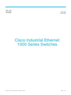
10 Or MicroLogix 1500 using a 1761-CBL-AM00 (8-pin mini-DIN to 8-pin mini-DIN) cable or equivalent. This type of connection will cause damage to the RS-232/485 communication port (Channel 0) of the MicroLogix 1100 and/or the controller itself. Communication pins used for RS-485 communications are alternately used for 24V power on the other MicroLogix Controllers . 11 Publication 1763-IN001C-EN-P - June 2015 Mounting DimensionsATTENTIONV ertical mounting is not supported due to thermal careful of metal chips when drilling mounting holes for your controller or other equipment within the enclosure or panel. Drilled fragments that fall into the controller could cause damage.