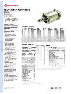
Transcription of Microsol 15 mm - IMI Precision
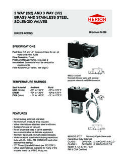
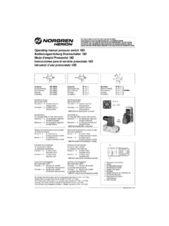
1 Microsol 15 mm Microsol 15 mm 2/2 & 3/2-way valves For lubricated and unlubricated compressed air, neutral liquids or gases Poppet valve, directly actuated with spring return Microsol interface: pilot operated poppet valve, servo assisted High cycle rate of up to 2000 cycles per minute Long life - in excess of 100 million cycles*. * Hit & Hold valves: 10 million cycles Flange mounted Response time: 8 - 10 ms Operating pressure: see technical data Description Solenoid valve for air, and neutral liquids or gases Switching function: normally closed and normally open 2 2. Flow direction: determined Fluid temperature: -10 C up to +30 C. Ambient temperature: -10 C up to +50 C 1 1. Mounting position: as required Symbol 1: 2/2 NC Symbol 2: 2/2 NO.
2 2 2. Materials Body: for 2/2 valves PPS, for 3/2 valves PPS, PA, Stainless steel Seat seal: NBR 1 3 1 3. Internal parts: Stainless steel, PA 6/6 Symbol 3: 3/2 NO Symbol 4: 3/2 NC. 2 2 2. 1 1 3 1 3. Symbol 5: 2/2 NC Symbol 6: 3/2 NC Symbol 7: 3/2 NO. NC: Normally closed NO: Normally open Technical data Connection DN kv-Value Part number Operating Function Manual Hit & Hold * Voltage Power Symbol /. mm pressure override consumption Drawing l/min m3/h bar 2/2 Direct acting valves / standard models Flange 01-211P202-H0+63111+AYZ 0 - 10 NC No No 24V DC 1/1. Flange 01-221P202-H0+631A1+AYZ 0 - 10 NO No No 24V DC 2/2. 3/2 Direct acting valves Flange 01-311P1011H0+61111+AYZ 0 - 10 NC Push only No 24V DC 4/4. Flange 01-321P1011H0+631A1+AYZ 0-6 NO No No 24V DC 3/4.
3 2/2 Direct acting valves / high flow models Flange 01-211P-036H0+63111+AZN 0-6 NC No Yes 24V DC 12 / 5/3. 3/2 Interface valves Flange 01-312E-06-HP+A1171+AYV - 10 NC Push only No 24V DC 6/6. Flange 01-322E-06-HP+C31G1+AYZ - 10 NO No No 24V DC 7/6. 3/2 Direct acting valves / intrinsically safe (IS) models**, labeling: EEx ia IIC T6 IINERIS 00 ATEX0031 X. Flange 01-311P-00-H0+F01003+BCC 0-7 NC Push only No 12V AC/DC 4/5. Flange 01-311P-00-H0+F01003+BDH 0-7 NC Push only No 24V AC/DC 4/5. Flange 01-311P-00-H0+H01014+AWD 4-7 NC Push only No 12V AC/DC 4/5. Flange 01-311P-00-H0+H01016+AYG 4-7 NC Push only No 24V AC/DC 4/5. 3/2 Direct acting valves / other options as used on M54 range**. Flange 01-311P101-H0+61511I+AWM 0 - 10 NC Push only No 12V DC 4/4.
4 Flange 01-311P101-H0+61511I+AYS 0 - 10 NC Push only No 24V DC 4/4. Flange 01-311P101-H0+11511I+AXX 0 - 10 NC Push only No 24V AC 1W 4/4. Flange 01-311P101-H0+11511I+BAU 0 - 10 NC Push only No 48V AC 1W 4/4. Flange 01-311P101-H0+11511I+BBJ 0 - 10 NC Push only No 110V AC 1W 4/4. Flange 01-311P101-H0+11511I+BCK 0 - 10 NC Push only No 220V AC 1W 4/4. * PWM energy saving option ** IP65 with connector 18 Microsol 15 mm Electrical characteristics Voltage range -10 % / +15 %. Protection class according to EN 60529: IP51 with connector 1. Electrical insulation: 1500V AC. Insulation class F (155 C). Electrical connection AMP +/- Drawing legend Drawing 1*. 1 9,4 2. Index Description 1 Wire (red) / pin +. 2 Wire (black) / pin . 41. M3x3.
5 AMP 2,8 x 0,5. 3 Manual override A. M3. 4 For NC models 8,2. 5 For NO models 14,2. 6 Mounting pattern 7 9,7. 3,8 17,2. 7. The recommended mounting screw A. tightening torque is Nm. 15,2. 3,8. 2. 2,2. 20,7 7,4. All solenoids are supplied with mounting screws and gasket. 1. 3. Warning for Hit and Hold valves: damage could be caused to the valve if wired incorrectly. 6. Further options on request Drawing 2 *. - Switching function (NO, Universal, Latching). - Operating pressure 1 9,4 2. - Vacuum - Materials - Manual override - Voltage M3x3. 46,2. AMP 2,8 x 0,5. A. M3. - Electrical connection - Power consumption 8,2. 14,2. 7 9,7. 3,8 17,2. A. 15,2. 3,8. 2. 2,2. 20,7 7,4. 1. 3. 6. * Dimensions in mm 19. Microsol 15 mm Drawing legend Drawing 3 *.
6 1 9,4 2. Index Description 1 Wire (red) / pin +. 2 Wire (black) / pin . 3 Manual override 48. M3x3. AMP 2,8 x 0,5. 2,2. 4 For NC models M3. 5 For NO models 6,9. 6 Mounting pattern A. 14,2 9,7. The recommended mounting screw 7. 7 3,8 17,2. tightening torque is Nm. A. All solenoids are supplied with mounting screws and gasket. 15,2. 3,3. Warning for Hit and Hold valves: damage could be caused to the valve if wired incorrectly. 2. 6. 4. 20,7 7,4. 1. 3,3. 6. Drawing 4 * Drawing 5 *. 1 9,4 2 M3x31 9,4 2. M 3x3. AMP 2,8 x 0,5. 46,2. AMP 2,8x0,5. 41. 3 A A. M3. M3. 3. 3. 11. 8,2. 8,2. 14,2 9,7 14,2 9,7. 7. 3,8 17,2 3 3,8 17,2. A A. 3,8. 3,8. 15,2. 15,2. 3 3. 1,9. 1,9. 20,7 7,4 20,7 7,4 2. 2. 1 1. 3,8. 3,8. 6 6. Drawing 6 *. 9,4. M3.
7 1 2. 6. 3,1+- 0,1. M3 x 25. 1. 7,4. M3. 1,4. 54. 2. 5 5. 32,5. AMP 2,8x0,5. 3. 18. 9,7. 3,1(3x) 22 6,5 9,7. 41,5 15,2. 4. 47. 5. 3 7. * Dimensions in mm 20. Microsol 15 mm Accessories Electrical connector Subbase 1. Single connector M/P43082 1 station: N/S5001. Single connector LED+VDR 24V M/P43086 2 stations: N/B5002. Single connector LED+VDR 110V M/P43148 3 stations: N/B5003. Single connector LED+VDR 220V M/P43087 4 stations: N/B5004. Single connector & 1 m flying lead M/P43066 5 stations: N/B5005. 6 stations: N/B5006. Electrical connector * Subbase *. 15,5 +0,1 50,3. AMP. 3,5 25 9,4+- 0,1 2,8x0,5. 1 23,5 3. 15,5 +0,1. 24. 4,7. M3. 15. M5. 24,5. 39,5. R. 35. 3. 4,4. 15. P A. 4,5. Pg7 14 = =. M3 (x2) 15. 2,8. 8 15. 7,75. M5.
8 = =. 9,7. 9,4. 15. M5. 0,8. 12,5 18,7 7,25. Drawing legend Subbase *. AMP. 53 2,8x0,5. Number of stations Length (L). 10. 2 32. 3 48. 24. 7. 39,5. M5. M5. 4 64. R R. M5. 5 80 A A1 A2 An 20. 14. 6 96 PG7 P P. M5. 10. M3 (x2) 8 16 8. 4,5. 4,4. M5. 15 L. 3,2. 9,4. 15. 3,2. 12,2. 15 0,8 7,25. 18,7 7,75. * Dimensions in mm Please find the safety instructions for the FAS range on page 318. 21.