Transcription of Model 3100L - directeddealers.com
1 Model 3100 LInstallation Guide 2008 Directed Electronics Vista, CA n3100l 2008 -122 2008 Directed Electronics Vista, CAtable of contentsAvital , Bitwriter , DEI , Doubleguard , ESP , FailSafe , Ghost Switch , Learn Routine , Nite-Lite ,Nuisance Prevention Circuitry , NPC , Revenger , Silent Mode , Soft Chirp , Stinger , Valet , VehicleRecovery System , VRS , and Warn Away are all Trademarks or Registered Trademarks of DirectedElectronics, is includedWhat Is Included.. 2 Wiring Quick Reference Guide.. 3 Primary Harness (H1) Wire Connection Guide.. 4 Door Lock Harness (H2) Wire Connection Guide.. 8 Type A Door Locks: Positive-Triggered, Relay Driven Systems .. 9 Type B Door Locks: Negative-Triggered, Relay Driven Systems (Type B) .. 10 Type C Door Locks: Reversing Polarity Systems . 11 Type D Door Locks: Adding One or More After-Market Actuators.
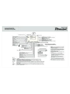
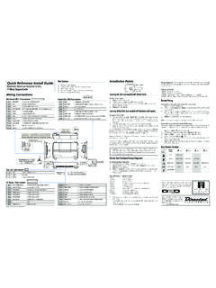
2 12 Type E Door Locks: Electrically Activated Vacuum .. 13 Type F Door Locks: One-Wire System .. 14 Type G Door Locks: Positive (+) Multiplex .. 15 Type H Door Locks: Negative (-) Multiplex .. 16 Starter Interrupt Harness (H3)Wire Connection Guide.. 17 Plug-In LED and Valet/Program Switch.. 17 Internal Programming Jumper.. 18On-Board Dual Stage Zone 2 Impact Sensor.. 19 Bypassing Sensor Inputs.. 19 Transmitter/Receiver Remote ControlCode Learning.. 20 Transmitter Configuration.. 21 Operating Settings Remote Control Code Learning.. 22 Features Menu.. 23 Feature Descriptions.. 24 Nuisance Prevention Circuitry .. 25 Table of Zones.. 25 Troubleshooting.. 26 The control module Two 3-button remote transmitters The plug-in LED system status indicator The plug-in Valet/Program switch An on-board zone 2 impact sensor A high-powered siren The 12-pin primary harness The 3-pin door lock harness The plug-in starter interrupt harness 2008 Directed Electronics Vista, CA3wiring quick reference guide4 2008 Directed Electronics Vista, CAprimary harness (H1) wire connection guide_____This wire supplies (-) ground as long as the system is armed.
3 This output ceases as soon as the system is can be used to turn on an optional sensor or to control an optional accessory, such as a window module or shipped, this wire should be connected to the (+) parking light wire. If the light flash polarity jumper insidethe control module is moved to the opposite position (see Internal Programming Jumpersection of this guide),this wire supplies a (-) 200 mA output. This is suitable for driving (-) light control wires in Toyota, Lexus, BMW,some Mitsubishi, some Mazda, and other Model cars. (+) Positive Light Flash OutputH1/2 WHITE (+/-) selectable light flash outputH1/1 ORANGE (-) ground-when-armed 500 mA outputRED/WHITE(-) 200 mA CHANNEL 2 VALIDITY OUTPUTRED(+)12V CONSTANT POWER INPUTBROWN(+) SIREN OUTPUTYELLOW(+) IGNITION INPUT, ZONE 5 BLACK (-) CHASSIS GROUND INPUT VIOLET(+) DOOR TRIGGER INPUT, ZONE 3 BLUE(-) MULTIPLEX TRIGGER INPUT, ZONE 1 GREEN(-) DOOR TRIGGER INPUT, ZONE 3 BLACK/WHITE(-) 200 mA INTERIOR LIGHT ILLUMINATION OUTPUTWHITE/BLUE(-) 200 mA CHANNEL 3 VALIDITY OUTPUTWHITE(+/-) SELECTABLE LIGHT FLASH OUTPUTORANGE(-) 500 mA GROUND-WHEN-ARMED OUTPUT H1/1H1/2H1/3H1/4H1/5H1/6H1/7H1/8H1/9H1/1 0H1/11H1/12 2008 Directed Electronics Vista, CA5(-) Negative Light Flash OutputNOTE:For parking light circuits that draw 10 amps or more, the internal jumper must be switchedto a (-) light flash output.
4 (See the Internal Programming Jumper section of this guide.) P/N 8617or a standard automotive SPDT relay must be used on the H1/2 light flash output harness wire provides a (-) 200 mA output whenever the transmitter code controlling Channel 3 is received. Thisoutput will continue as long as that transmission is received. Use for options such as 551 TValet Start system,529T or 530 Tpower window controllers, etc. IMPORTANT! Never use this wire to drive anything except a relay or a low-current input! The tran-sistorized output can only provide 200 mA of current, and connecting directly to a solenoid, motor,or other high-current device will cause it to the H1/4 BLACK/WHITE wire to an optional relay for interior light illumination (p/n 8617or standardautomotive SPDT relay).IMPORTANT!This output is only intended to drive a relay.
5 It cannot be connected directly to the domelight circuit, as the output is not able to support the current draw of one or more light BLACK/WHITE (-) interior light illumination outputH1/3 WHITE/BLUE (-) channel 3 output6 2008 Directed Electronics Vista, CAMost vehicles use negative door trigger circuits. Connect the green wire to a wire which shows ground when anydoor is opened. In vehicles with factory delays on the domelight circuit, there is usually a wire that is unaffectedby the delay circuitry. This wire will report Zone wire will respond to a negative input with an instant trigger. Inputs shorter than seconds will triggerthe Warn Away response, while triggers longer than seconds will instantly trigger the full alarm cycle. Thiswire is ideal for hood and trunk pins and will report on Zone 1. This wire can also be used with DEI s 506T GlassBreakage Sensor, as well as other DEI single stage sensors.
6 The H1/6 BLUE multiplex trigger wire can be used to shunt sensors during operation, using the auxiliary chan-nels. When any of the auxiliary channels are transmitted, the H1/6 BLUE wire monitors for a ground. If groundis detected within 5 seconds of transmission, the sensors and the multiplex trigger input on the BLUE wire willbe shunted until 5 seconds after the ground is removed. This allows the customer to access the trunk, remotestart the vehicle, or roll the windows down without first disarming the alarm. (See Bypassing Sensor Inputssection of this guide.)This wire is used in vehicles that have a positive (+) switched dome light circuit. Connect the violet wire to a wire that shows (+)12V when any door is opened, and ground when the door is closed. This wire will reportZone VIOLET (+) door trigger input, zone 3H1/6 BLUE (-) multiplex trigger input, zone 1H1/5 GREEN (-) door trigger input, zone 3 2008 Directed Electronics Vista, CA7 Remove any paint and connect this wire to bare metal, preferably with a factory bolt rather than your own screw.
7 (Screws tend to either strip or loosen with time.) We recommend grounding all your components, including thesiren, to the same point in the vehicle. See the following this wire to an ignition source. This input must show (+)12V with the key in run position and duringcranking. Make sure that this wire cannot be shorted to the chassis at any point. This wire will report Zone this to the red wire of the siren. Connect the black wire of the siren to (-) chassis ground, preferably atthe same point you connect the control module s black ground BROWN (+) siren outputH1/9 YELLOW (+) ignition input, zone 5H1/8 BLACK (-) chassis ground connection8 2008 Directed Electronics Vista, CABefore connecting this wire, remove the supplied fuse. Connect to the positive battery terminal or the constant12V supply to the ignition switch. NOTE: Always use a fuse within 12 inches of the point you obtain (+)12V power.
8 Do not use the15A fuse in the harness for this purpose. This fuse protects the module the system receives the code controlling Channel 2, for longer than seconds, the red/white wire willsupply an output as long as the transmission continues. This is often used to operate a trunk/hatch release orother relay-driven !Never use this wire to drive anything but a relay or a low-current input! The transis-torized output can only supply 200 mA of current. Connecting directly to a solenoid, motor, or otherhigh-current device will cause it to lock harness (H2) wire connection guide_____This security system can control two common power door lock types without any additional parts! With certain vehicles, or if an actuator is to be installed, either a 451 MDoor Lock Relay Satellite or two relays willbe (+) LOCK, (-) UNLOCK OUTPUTOPENUNLESS USING 451 MGREEN(-) LOCK, (+) UNLOCK OUTPUTH2/1H2/2H2/3H1/12 RED/WHITE channel 2, (-) 200mA output H1/11 RED (+)12V constant power input 2008 Directed Electronics Vista, CA9 This security system can control Type A door locks directly, with no additional parts.
9 The switch will have threewires on it, and one will test (+)12V constantly. The others will alternately pulse (+)12V when the switch ispressed to the lock or unlock you cannot get to the switch, and you find a set of wires that pulse (+)12V alternately on lock and unlock,you must take care to ensure that it is not a Type C direct-wire system. IMPORTANT! If you mistake a Type C direct-wired system for a Type A positive-pulse system, themodule will be damaged!Here is a test: Cut the wire which pulses (+)12V on lock, and then operate the switch to unlock. If all doors unlock, the vehicle uses a Type A system. If you lose all door lock operation in both directions, you are operating the master switch in a Type C system. If one or more, but not all, motors stop operating, you have cut a wire leading directly to one or more the wire and look for another domestically-made GM vehicles use Type A locks.
10 However, many more GM vehicles are Type C than in pre-vious years. The full-size pickups (1989-later), many of the S10 Blazers, the Corvette, '95 Cavalier/Sunfire 1993and newer, Camaro/Firebird all use Type C door locks, and cannot be controlled without a 451M! Almost all domes-tically-built Fords are Type C. Ford builds almost no Type A systems. Chrysler builds both Type A and Type C, sotest ! Remember that the functions of these wires reverse between Type A and Type B!type A: positive (+) 12V pulses from the switch to the factory relays10 2008 Directed Electronics Vista, CAThis system is common in many Toyota, Nissan, Honda, and Saturn models, as well as Fords with remote-con-trolled door lock/unlock (some other Fords also use Type B). The switch will have three wires on it, and one wire will test ground all the time. One wire will pulse (-) whenthe switch locks the doors, and the other wire will pulse (-) when the switch unlocks the doors.