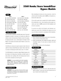
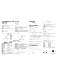
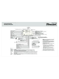
Transcription of Model 552T - directeddealers.com
1 Model 552 TInstallation Guide2001 Directed Electronics, Inc. Vista, CA N552T 7-01 NEW! Outboard HF Plus Receiverfor Extended Range2 2000 Directed Electronics, Inc. Vista, CAtable of contentsBitwriter , Code Hopping , DEI , Doubleguard , ESP , FailSafe , Ghost Switch ,Learn Routine , Nite-Lite , Nuisance Prevention Circuitry , NPC , Revenger , SilentMode , Soft Chirp , Stinger , Valet , Vehicle Recovery System , VRS , and WarnAway are all Trademarks or Registered Trademarks of Directed Electronics, Quick Reference Guide.. 3 Warning! Safety First.. 4 Installation Points to Remember.. 5 Deciding On Component Locations.. 6 Control Module.. 6 Valet /Program Switch .. 6 Status LED .. 7 Optional Starter Kill Relay .. 7 Finding The Wires You Need.
2 8 Obtaining Constant 12V .. 8 Finding the 12V Switched Ignition Wire .. 8 Finding the Starter Wire.. 9 Finding a (+/-) Parking Light Wire .. 9 Finding the Accessory Wire .. 10 Finding the Tachometer Wire .. 10 Finding the Wait-To-Start Bulb Wire For Diesels .. 11 Wiring Diagrams.. 12 Primary Harness (H1) Wiring Diagram .. 12 Remote Start Ribbon Harness Wiring Diagram . 12 Heavy Gauge Relay Satellite Wiring Diagram . 13 Auxiliary Harness (H2) Wiring Diagram .. 13 Remote Start Harness (H3) Wiring Diagram.. 13 Primary Harness (H1) Wire Connection Guide. 14 Relay Satellite Key Switch Interface WireConnection Guide.. 17 Auxiliary Harness (H2) Wire Connection Guide. 18 Remote Start Harness (H3)Wire Connection Guide.. 19 Neutral Safety Switch Interface.
3 21 Testing the Neutral Safety Switch .. 211995 and Newer Vehicle Anti-Theft Systems (Immobilizers).. 23 Passlock I and Passlock II (PL-1 and PL-2).. 23 Passlock II (PK-3), Transponder-Based Systems . 24 Bypassing GM Vehicle Anti-Theft Systems.. 24 Optional Anti-Grind Relay.. 25 Plug-in LED and Valet/Program Switch.. 26 Programmer Interface, 3-Pin Port.. 27 Door Lock Harness (H4) Wire Connection Guide. 27 Positive-Triggered, Relay DrivenSystems (Type A) .. 27 Negative-Triggered, Relay DrivenSystems (Type B) .. 29 Reversing Polarity System (Type C) .. 30 Adding One or More After-MarketActuators (Type D) .. 31 Electrically Activated Vacuum (Type E) .. 32 One-Wire System (Type F) .. 32 Positive (+) Multiplex (Type G) .. 33 Negative (-) Multiplex (Type H).
4 34 Programming Jumpers.. 35 Light Flash (+)/(-) .. 35 Tach Threshold On/Off .. 35 Transmitter/Receiver Learn Routine.. 36 Transmitter Configurations.. 38 Single Button Arm/Disarm Configuration .. 38 Separate Button Configuration.. 38 Operating-Settings Learn Routine.. 39 Feature Menus.. 41 Menu #1 .. 41 Menu #2 .. 41 Feature Descriptions.. 42 Menu #1 .. 42 Menu #2 .. 43 Tach Learning.. 44 Shutdown Diagnostics.. 45 Rapid Resume Logic.. 46 Timer Mode.. 46 Valet Mode.. 47 Safety Check.. 47 Troubleshooting.. 48 The Bitwriter (p/n 998T)requires chip version ornewer to program this unit. 2000 Directed Electronics, Inc. Vista, CA3wiring quick reference guide4 2000 Directed Electronics, Inc. Vista, CAwarning! safety firstThe following safety warnings must be observed at all times: Due to the complexity of this system, installation of this product must only be performed by an authorizedDEI dealer.
5 When properly installed, this system can start the vehicle via a command signal from the remote controltransmitter. Therefore, never operate the system in an area that does not have adequate ventilation. The fol-lowing precautions are the sole responsibility of the user; however, authorized DEI dealers should make thefollowing recommendations to all users of this system: 1. Never operate the system in an enclosed or partially enclosed area without ventilation (such as a garage). 2. When parking in an enclosed or partially enclosed area or when having the vehicle serviced, the remotestart system must be disabled using the installed toggle switch. 3. It is the user's sole responsibility to properly handle and keep out of reach from children all remotecontrol transmitters to assure that the system does not unintentionally remote start the vehicle.
6 USER MUST INSTALL A CARBON MONOXIDE DETECTOR IN OR ABOUT THE LIVING AREA ADJACENTTO THE VEHICLE. ALL DOORS LEADING FROM ADJACENT LIVING AREAS TO THE ENCLOSED OR PAR-TIALLY ENCLOSED VEHICLE STORAGE AREA MUST AT ALL TIMES REMAIN CLOSED. Use of this product in a manner contrary to its intended mode of operation may result in property damage,personal injury, or death. Except when performing the Safety Check outlined in this installation guide, (1)Never remotely start the vehicle with the vehicle in gear, and (2) Never remotely start the vehicle with thekeys in the ignition. The user will be responsible for having the neutral safety feature of the vehicle period-ically checked, wherein the vehicle must not remotely start while the car is in gear.
7 This testing should beperformed by an authorized DEI dealer in accordance with the Safety Check outlined in this product instal-lation guide. If the vehicle starts in gear, cease remote start operation immediately and consult with the userto fix the problem immediately. After the remote start module has been installed, test the remote start module in accordance with the SafetyCheck outlined in this installation guide. If the vehicle starts when performing the Neutral Safety ShutdownCircuit test, the remote start unit has not been properly installed. The remote start module must be removedor properly reinstalled so that the vehicle does not start in gear. All installations must be performed by anauthorized DEI dealer. OPERATION OF THE REMOTE START MODULE IF THE VEHICLE STARTS IN GEAR IS CON-TRARY TO ITS INTENDED MODE OF OPERATION.
8 OPERATING THE REMOTE START SYSTEM UNDER THESECONDITIONS MAY RESULT IN PROPERTY DAMAGE OR PERSONAL INJURY. IMMEDIATELY CEASE THE USE OFTHE UNIT AND REPAIR OR DISCONNECT THE INSTALLED REMOTE START MODULE. DEI WILL NOT BE HELDRESPONSIBLE OR PAY FOR INSTALLATION OR REINSTALLATION COSTS. 2000 Directed Electronics, Inc. Vista, CA5installation points to rememberqIMPORTANT! This product is designed for fuel-injected, automatic transmission vehicles it in a standard transmission vehicle is dangerous and is contrary to its intended use. Please read this entire installation guide before beginning the installation. The installation of this remotestart system requires interfacing with many of the vehicle s systems. Many new vehicles use low-voltage ormultiplexed systems that can be damaged by low resistance testing devices, such as test lights and logicprobes (computer safe test lights).
9 Test all circuits with a high quality digital multi-meter before making con-nections. Do not disconnect the battery if the vehicle has an anti-theft-coded radio. If equipped with an air bag, avoiddisconnecting the battery if possible. Many airbag systems will display a diagnostic code through theirwarning lights after they lose power. Disconnecting the battery requires this code to be erased, which canrequire a trip to the dealer. Check with the customer on status LED location. Remove the domelight fuse. This prevents accidentally draining the battery. Roll down a window to avoid being locked out of the car. q Test all functions. The "Using Your System" section of the Owner's Guide is very helpful when testing. Complete the vehicle Safety Checkoutlined in this manual prior to the vehicle the installationbefore beginning the installation6 2000 Directed Electronics, Inc.
10 Vista, CAdeciding on component locationsThings to remember when positioning the control module: Never place the control module in the engine compartment! The first thing a thief will do when hot-wiring a vehicle is to remove the driver's side under-dash panel toaccess the starter and ignition wires. You should therefore avoid placing the control module just behind thedriver s side dash to prevent it from being easily disconnected during a theft attempt. When locating the control module, try to find a secure location that will not require you to extend the harnesswires (they are meters long). Keep the control module away from the heater core (or any other heat sources) and any obvious leaks. The higher the control module is in the vehicle, the better the transmitter range will be.