Transcription of Model: RXT - kohlerpower.com
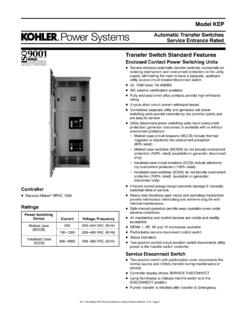
1 Model: RXT. Automatic Transfer Switch 100--400 Amps Model RXT Automatic Transfer Switch The Model RXT automatic transfer switch is designed for use only with Kohlerr generator sets equipped with RDC2 or DC2. generator set/transfer switch controls. The transfer switch operation is controlled by the RDC2/DC2 controller. Standard Features D Allows utility voltage display on the RDC2/DC2 generator set/transfer switch controller, available exclusively on Kohlerr residential and light commercial generator sets D UL listed d Models with load centers, UL 67 listed, file # E251086. d Models without load centers, UL 1008 listed, file # E58962.
2 D CSA certification, file # LR58301, is available for: d Standard ATS without load center (single and three-phase). d Service entrance ATS 100 and 200 amp models D Corrosion-resistant NEMA 3R aluminum enclosure d Padlockable d Approved for indoor or outdoor installation d ANSI 49 gray D NEMA 1 enclosure available on 100 amp load center models D Contactor electrically and mechanically interlocked D Double throw inherently interlocked design D Contactor manually operable for maintenance purposes D Silver alloy main contacts D Transfer switches are 100% equipment rated and can be applied at the rated current without derating (non-service entrance models).
3 D Service entrance models include disconnect circuit breaker on the utility (normal) source side (80% rated). D Five-year limited warranty Covers have been removed for illustration. Standard Interface Board D Standard interface board connects to the Model RDC2 or DC2 generator set/transfer switch controller. Available Models D Includes a load control contact that provides a 5 minute time D 100, 200, and 400 amp standard and service delay for startup of selected loads after transfer to the entrance models are available. emergency source. Use for large motor loads. D 150 and 300 amp service entrance models are also available.
4 Combined Interface/ Load D Combined interface/ load management board is Management Board available on single-phase standard and service D Optional combined interface/ load management board entrance models. (Not available on 3-phase or load replaces the standard interface board and connects to the center models.) Model RDC2 or DC2 generator set/transfer switch controller. D 100 amp standard single-phase models are available D The combined board is available on single-phase standard with or without a 16-space load center. Up to 8 and service entrance models. tandem breakers can be used for a total of 24 (Not available on 3-phase or load center models.)
5 Circuits. D The combined board automatically manages up to six D 100amp standard single phase model with a residential loads: 12-space load center and a NEMA 1 enclosure is d Up to four customer-supplied power relay modules can available as a standalone non-configurable spec be connected for management of non-essential (GM85273-SA_). secondary loads. D See page 7 for more information. d Two HVAC relays are included for control of two independent air conditioner loads. G11-140 (Model RXT Automatic Transfer Switch) 3/18e Page 1. Specifications Codes and Standards Standard Interface Board The ATS meets or exceeds the requirements of the following Controller interface connections #20 AWG shielded twisted-pair specifications: A and B Belden 9402 or 8762 or equivalent D Underwriters Laboratories UL 67, Enclosed Panel Boards Controller interface connections #12--20 AWG (load center models) file # E251086.
6 PWR and COM (see ATS Installation Manual). D Underwriters Laboratories UL 1008, Standard for Automatic Load control contact rating 10 A @ 250 VAC. Transfer Switches for Use in Emergency Systems, file Load control connections #12--18 AWG # E58962. Note: For combined interface/load management board D Underwriters Laboratories UL 508, Standard for Industrial specifications, see page 3. Control Equipment D CSA certification available, file # LR58301 (not available for 150, 300, or 400 amp service entrance or 100 amp load Environmental Specifications center models). Must be selected when the transfer switch Operating temperature 20_C to 70_C ( 4_F to 158_F) is ordered.
7 Storage temperature 40_C to 85_C ( 40_F to 185_F) D NFPA 70, National Electrical Code Humidity 5 to 95% noncondensing D NFPA 110, Emergency and Standby Power Systems D NEMA Standard IC10--1993, AC Automatic Transfer Switches Cable Sizes AL/CU UL-Listed Solderless Screw-Type Terminals for External Power Connections Switch Range of Wire Sizes, Cu/Al Size, Amps Switch Phases Normal and Emergency Load Neutral Ground (5) #12 to 250 KCMIL (Cu) or Standard 1 (1) #14 -- 1/0 AWG (1) #14 1/0 AWG. (5) #10 to 250 KCMIL (Al). 12-space per customer-supplied (13) #4 -- 14 AWG or load center 1 (1) #14 1/0 AWG (9) #6 #14 AWG.
8 Circuit breaker (1) #6 2/0 AWG. (NEMA 1) (4) #14 -- 1/0 AWG. 16-space (27) #4 -- 14 AWG or 100 per customer-supplied load center 1 (1) #14 1/0 AWG (3) #4 -- 1/0 AWG or circuit breaker (NEMA 3R) (1) #6 2/0 AWG. Service Normal: (1) #12 2/0 AWG (5) #12 to 250 KCMIL (Cu) or 1 (1) #14 1/0 AWG. Entrance Emerg: (1) #14 1/0 AWG (5) #10 to 250 KCMIL (Al). (3) #4 AWG 600 KCMIL (4) #14 1/0 AWG. 3-Phase 3 (1) #14 1/0 AWG (1) #14 1/0 AWG. (6) 1/0 AWG 250 KCMIL (9) #14 -- #6 AWG. 150 Service Normal: (1) #4 300 KCMIL (5) #12 to 250 KCMIL (Cu) or 1 (1) #6 250 KCMIL. 200 Entrance Emerg: (1) #6 -- 250 KCMIL (5) #10 to 250 KCMIL (Al).
9 Standard 1 (5) #12 to 250 KCMIL (Cu) or (9) #14 #4 AWG. 200 (1) #6 AWG 250 KCMIL (1) #6 250 KCMIL. 3-Phase 3 (5) #10 to 250 KCMIL (Al) (4) #14 -- 1/0 AWG. Normal: : (1) #1 -- 600 KCMIL. 300 Service (3) #4 AWG 600 KCMIL. 1 or (2) #1 250 KCMIL (2) #6 250 KCMIL (6) #6 3/0 AWG. 400 Entrance (6) 1/0 AWG 250 KCMIL. Emerg: (2) #6 -- 250 KCMIL. Standard 1. 3-pole (2) #6 250 KCMIL (2) #6 250 KCMIL. 3 (3) #4 AWG 600 KCMIL. 400 208-240 V (6) #6 3/0 AWG. (6) 1/0 AWG 250 KCMIL. 3 or 4 pole (1) #4 600 KCMIL (1) #4 600 KCMIL. 3. 480 V (2) 1/0 250 KCMIL (2) 1/0 250 KCMIL. Note: Data is subject to change. Refer to the transfer switch dimension drawings and wiring diagrams for planning and installation.
10 G11-140 (Model RXT Automatic Transfer Switch) 3/18e Page 2. Optional Combined Interface/Load Management Board The RXT transfer switch is available with either a standard Priority Setting interface board or a combined interface/ load management D Loads are added and shed according to their priority. Load 1. board. The combined board allows load management as is the top priority, which is added first and shed last. Load 6. described below. is the lowest priority. D Less critical loads can be turned off automatically when Load Management essential appliances are running. D The combined load management board disconnects D Load priorities are hard-wired at installation.
