Transcription of Monitor and Sentinel User's Guide - otronix.com
1 WorkHorse Monitor / Sentinel user s Guide P/N 957-6228-00 (November 2007) Table of Contents Monitor and Sentinel User's Guide .. 1 1 Technical Support .. 1 Overview .. 1 Hardware Overview .. 2 Battery Packs and power 3 Optional External Battery Pack .. 5 Flash Memory Card .. 5 Serial Communication 6 Deployment Overview .. 7 Software Overview .. 7 Installing the Software .. 9 WorkHorse Preparation .. 10 Visual Inspection .. 12 Seal the WorkHorse for Deployment .. 13 Install and Connect the Sentinel 14 Check all Mounting Hardware is Installed .. 19 Bench Test .. 20 Setup the WorkHorse ADCP .. 20 Connecting to the WorkHorse .. 22 Changing the Baud Rate in the 24 Testing the 25 Compass 26 Preparing for Calibration .. 26 Compass Calibration Verification .. 27 Compass Calibration Procedure.
2 27 Optional Pressure Sensor Preparation .. 30 Collecting Self-Contained Data .. 32 Recover Data with WinSC .. 41 Viewing Data with 42 Collecting Real-Time 43 Sending the Commands to the WorkHorse ADCP .. 48 Viewing Data in Real-Time .. 49 Where to Find More 51 List of Figures Figure 1. WorkHorse Sentinel Exploded View .. 2 Figure 2. WorkHorse Sentinel Battery Pack .. 4 Figure 3. External Battery Pack 5 Figure 4. Memory Card 5 Figure 5. I/O Cable Wiring Diagram .. 6 Figure 6. Visual Inspection 11 Figure 7. WorkHorse Connections .. 20 Figure 8. Compass Calibration .. 28 NOTES Monitor and Sentinel User's Guide P/N 957-6228-00 (November 2007) page 1 Monitor and Sentinel User's Guide Introduction Thank you for purchasing the Teledyne RD Instruments (TRDI) WorkHorse Monitor / Sentinel Acoustic Doppler Current Profiler (ADCP).
3 This user s Guide will lead you through the steps required for a successful deployment. Please read the entire Guide , and then follow the instruc-tions in the order they are presented. Additional information can be found in the Wo r k H o r s e Te c h -nical Manual that is supplied on CD-ROM. NOTE. To purchase a printed copy of the WorkHorse documentation (includes the WorkHorse Technical Manual and software guides), contact our Customer Service department at or call (858) 842-2600 and order the WorkHorse Manual kit. Technical Support If you have technical issues or questions involving a specific application or deployment with your instrument, contact our Field Service group: Teledyne RD Instruments Teledyne RD Instruments Europe 14020 Stowe Drive Poway, California 92064 2A Les Nertieres 5 Avenue Hector Pintus 06610 La Gaude, France Phone +1 (858) 842-2600 Phone +33(0) 492-110-930 FAX +1 (858) 842-2822 FAX +33(0) 492-110-931 Sales Sales Field Service Field Service Customer Service Administration Web.
4 24/7 Technical Support +1 (858) 842-2700 Monitor and Sentinel User's Guide page 2 Teledyne RD Instruments Overview The first step is to become familiar with the Monitor / Sentinel ADCP. Read the short descrip-tions of the hardware and software that comes with the WorkHorse. This Section Covers: Hardware Overview Battery Packs and power Overview Serial Communication Overview Deployment Overview Software Overview Installing the Software Hardware Overview The WorkHorse Sentinel ADCP system consists of an ADCP, cables, battery pack, flash mem-ory card, and software. The WorkHorse Sentinel can also be used for direct-reading current profile operation. The ADCP requires the addition of a Windows compatible computer to configure the ADCP and replay collected data.
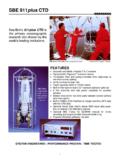
5 The WorkHorse Monitor system consists of an ADCP, cables, and software. The Monitor does not include the internal battery or flash memory and therefore uses a shorter housing. The Sen-tinel and Monitor use the same electronics. URETHANE FACEBEAM 3 MARKTHERMISTORPRESSURE SENSOR(OPTIONAL)TRANSDUCER HEADHOUSINGMEMORY CARDINTERNAL BATTERYPAC KEND-CAPI/O CABLE CONNECTOR Figure 1. WorkHorse Sentinel Exploded View Monitor and Sentinel User's Guide P/N 957-6228-00 (November 2007) page 3 The transducer assembly contains the transducer ceramics and electronics. Standard acoustic frequencies are 600 and 1200 kHz. See the outline drawings in the WorkHorse Technical Manual for dimensions and weights. I/O Cable Connector Input/Output (I/O) cable connects the WorkHorse ADCP to the com-puter.
6 Beam-3 Mark The Beam-3 mark shows the location of Beam-3 (Forward). Urethane Face The urethane face covers the transducer ceramics. Never set the transducer on a hard surface. The urethane face may be damaged. Housing The WorkHorse housing allows deployment depths to 200 meters. Thermistor The Thermistor measures the water temperature. Pressure Sensor The optional pressure sensor measures water pressure (depth). Transducer Head The WorkHorse electronics and transducer ceramics are mounted to the transducer head. The numbers embossed on the edge of the transducer indicates the beam number. When assembling the unit, match the transducer beam number with the Beam 3 mark on the end-cap. End-Cap The end-cap holds the I/O cable connector. When assembling the unit, match the Beam 3 mark on the end-cap with beam 3 number on the transducer.
7 Internal Battery Pack WorkHorse Sentinel ADCPs use an internal battery pack to provide power to the ADCP. Flash Memory Card WorkHorse Sentinel ADCPs come standard with one memory card. Two PCMCIA memory cards slots are available, with the total memory capacity not to exceed 1GB. Battery Packs and power Overview WorkHorse Monitor / Sentinel ADCPs require +20 to 50 VDC to operate. The standard AC Adapter runs on any standard AC power and supplies +48 VDC to run the WorkHorse when the batteries are not connected. The WorkHorse Sentinel s internal battery supplies +42 VDC. NOTE. The AC Adapter input voltage is sufficient to override the internal battery voltage ( the ADCP will draw all power from the AC adapter even if the battery is installed and connected). Always use the AC adapter when testing the ADCP to conserve the battery power .
8 Keep in mind the following about Sentinel battery packs: TRDI specifies its battery packs to have 450 Watt-hours (Wh) of usable energy at 0 C. A Standard WorkHorse battery packs hold 28 D-cell alkaline batteries with a voltage, when new, of approximately 42 VDC. When the capacity of a battery pack is 50% used, the voltage (measured across the battery connector under no-load conditions) falls to approximately 32 to 35 volts. However, keep in mind that this voltage is not an accurate predictor of remaining capacity. Monitor and Sentinel User's Guide page 4 Teledyne RD Instruments Transmitted power increases or decreases depending on the input voltage (within the voltage range of 20 to 50 VDC). A fresh battery provides +42 VDC. Batteries spend most of their life at a nominal voltage of +33 VDC.
9 NOTE. The transmitted power is decreased one DB if the input voltage drops from 42 VDC to 33 VDC. For a 600 kHz WorkHorse ADCP, each one DB drop will result in a decrease in range of one default depth cell. Batteries should be replaced when the voltage falls below 30 VDC (measured across the battery connector under no-load conditions). Battery packs differ from one to another. Store batteries in a cool dry location (0 to 21 degrees C). Do not store batteries inside the ADCP for extended periods. The batteries may leak. Use batteries within one year (shelf life). NOTE. Battery replacement induces both single and double cycle compass errors. The compass accuracy should be verified after replacing the battery pack. The compass does not have to be recalibrated if the compass verification passes specification.
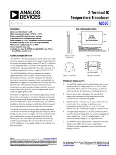
10 These compass effects can be avoided by using an optional external battery pack. The optional external battery housing holds two batteries, and can easily be replaced on-site. If the optional external battery is placed a minimum of 30 cm away from the ADCP, no compass calibration will be required. INTERNALI/O CABLETHREADEDROD (4)WING NUT (4)WASHER (4)RUBBER BANDSBATTERY PACKLOCK WASHER (4)BATTERY CABLESPACER (4)DESICCANTRUBBER BANDSUPPORT PLATE Figure 2. WorkHorse Sentinel Battery Pack Monitor and Sentinel User's Guide P/N 957-6228-00 (November 2007) page 5 Optional External Battery Pack The optional External Battery Pack holds two 450 Watt-hours (Wh) batteries. To avoid affect-ing the compass, place the external battery case at least 30-cm away from the WorkHorse ADCP.