Transcription of MOSFET Device Physics and Operation
1 1 MOSFET Device Physicsand INTRODUCTIONA field effect transistor (FET) operates as a conducting semiconductor channel with twoohmic contacts thesourceand thedrain where the number of charge carriers in thechannel is controlled by a third contact thegate. In the vertical direction, the gate- channel -substrate structure (gate junction)can be regarded as an orthogonal two-terminaldevice, which is either a MOS structure or a reverse-biased rectifying Device that controlsthe mobile charge in the channel by capacitive coupling (field effect). Examples of FETsbased on these principles are metal-oxide-semiconductor FET ( MOSFET ), junction FET(JFET), metal-semiconductor FET (MESFET), and heterostructure FET (HFETs).
2 In allcases, the stationary gate- channel impedanceis very large at normal operating basic FET structure is shown schematically in Figure most important FET is the MOSFET . In a silicon MOSFET , the gate contactis separated from the channel by an insulating silicon dioxide (SiO2) layer. The chargecarriers of the conducting channel constitute an inversion charge, that is, electrons in thecase of ap-type substrate (n- channel Device ) or holes in the case of ann-type substrate(p- channel Device ), induced in the semiconductor at the silicon-insulator interface by thevoltage applied to the gate electrode. Theelectrons enter and exit the channel atn+sourceand drain contacts in the case of ann- channel MOSFET , and atp+contacts in the caseof ap- channel are used both as discrete devices and as active elements in digital andanalog monolithic integrated circuits (ICs).
3 In recent years, the Device feature size ofsuch circuits has been scaled down into the deep submicrometer range. Presently, m technology node for complementary MOSFET (CMOS) is used for very largescale ICs (VLSIs) and, within a few years, m technology will be available,with a commensurate increase in speed and in integration scale. Hundreds of millions oftransistors on a single chip are used in microprocessors and in memory ICs technology combines bothn- channel andp- channel mosfets to provide verylow power consumption along with high speed. New silicon-on-insulator (SOI) technologymay help achieve three-dimensional integration, that is, packing of devices into manyDevice Modeling for Analog and RF CMOS Circuit Ytterdal, Y.
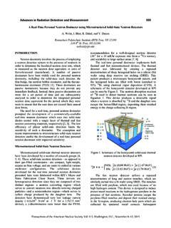
4 Cheng and T. A. Fjeldly 2003 John Wiley & Sons, LtdISBN: 0-471-49869-62 MOSFET Device Physics AND OPERATIONGateDrain SourceSemiconductor substrate Insulator Gate junction Substrate contact Conducting channelFigure illustration of a generic field effect transistor. This Device can be viewedas a combination of two orthogonal two-terminal deviceslayers, with a dramatic increasein integration density. Newimproved Device structuresand the combination of bipolar and field effect technologies (BiCMOS) may lead tofurther advances, yet unforeseen. One of the rapidly growing areas of CMOS is in analogcircuits, spanning a variety of applicationsfrom audio circuits operating at the kilohertz(kHz) range to modern wireless applications operating at gigahertz (GHz) THE MOS CAPACITORTo understand the MOSFET , we first have to analyze the MOS capacitor, which consti-tutes the important gate- channel -substrate structure of the MOSFET .
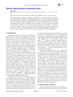
5 The MOS capacitoris a two-terminal semiconductor Device of practical interest in its own right. As indi-cated in Figure , it consists of a metal contact separated from the semiconductor bya dielectric insulator. An additional ohmiccontact is provided at the semiconductor sub-strate. Almost universally, the MOS structure utilizes doped silicon as the substrate andits native oxide, silicon dioxide, as the insulator. In the silicon silicon dioxide system,the density of surface states at the oxide semiconductor interface is very low comparedto the typical channel carrier density in a MOSFET . Also, the insulating quality of theoxide is quite contactFigure view of a MOS capacitorTHE MOS CAPACITOR3We assume that the insulator layer has infinite resistance, preventing any charge carriertransport across the dielectric layer when abias voltage is applied between the metal andthe semiconductor.
6 Instead, the applied voltage will induce charges and counter chargesin the metal and in the interface layer of thesemiconductor, similar to what we expect inthe metal plates of a conventional parallel plate capacitor. However, in the MOS capacitorwe may use the applied voltage to control the type of interface charge we induce in thesemiconductor majority carriers, minority carriers, and depletion , the ability to induce and modulate a conducting sheet of minority carriers atthe semiconductor oxide interface is the basis for the Operation of the Interface ChargeThe induced interface charge in the MOS capacitor is closely linked to the shape ofthe electron energy bands of the semiconductor near the interface.
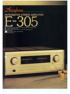
7 At zero applied volt-age, the bending of the energy bands is ideally determined by the difference in thework functions of the metal and the semiconductor. This band bending changes with theapplied bias and the bands become flat when we apply the so-called flat-band voltagegiven byVFB=( m s)/q=( m Xs Ec+EF)/q,( )where mand sare the work functions of the metal and the semiconductor, respectively,Xsis the electron affinity for the semiconductor,Ecis the energy of the conduction bandedge, andEFis the Fermi level at zero applied voltage. The various energies involvedare indicated in Figure , where we show typical band diagrams of a MOS capacitorat zero bias, and with the voltageV=VFBapplied to the metal contact relative to thesemiconductor oxide interface.
8 (Note that in real devices , the flat-band voltage may beqVFB m Vacuum levelV = 0Ec EFEv EgXs sV = VFBM etalOxide EFmEgqVFBEcEFsEvSemiconductor(a)(b)Figur e diagrams of MOS capacitor (a) at zero bias and (b) with an applied voltageequal to the flat-band voltage. The flat-band voltage is negative in this example4 MOSFET Device Physics AND Operation affected by surface states at the semiconductor oxide interface and by fixed charges inthe insulator layer.)At stationary conditions, no net current flows in the direction perpendicular to theinterface owing to the very high resistance of the insulator layer (however, this doesnot apply to very thin oxides of a few nanometers, where tunneling becomes important,see Section ).
9 Hence, the Fermi level willremain constant inside the semiconductor,independent of the biasing conditions. However, between the semiconductor and the metalcontact, the Fermi level is shifted byEFm EFs=qV(see Figure (b)). Hence, we havea quasi-equilibrium situation in which the semiconductor can be treated as if in MOS structure with ap-type semiconductor will enter theaccumulationregime ofoperation when the voltage applied betweenthe metal and the semiconductor is morenegative than the flat-band voltage (VFB<0 in Figure ). In the opposite case, whenV>VFB, the semiconductor oxide interface first becomes depleted of holes and weenter the so-calleddepletionregime. By increasing the applied voltage, the band bendingbecomes so large that the energy difference between the Fermi level and the bottom ofthe conduction band at the insulator semiconductor interface becomes smaller than thatbetween the Fermi level and the top of the valence band.
10 This is the case indicated forV=0 V in Figure (a). Carrier statistics tellsus that the electron concentration thenwill exceed the hole concentration near the interface and we enter still larger applied voltage, we finally arrive at a situation in which the electron volumeconcentration at the interface exceeds the doping density in the semiconductor. This isthe strong inversion case in which we have a significant conducting sheet of inversioncharge at the symbol is used to signify the potential in the semiconductor measured relativeto the potential at a positionxdeep inside the semiconductor. Note that becomespositive when the bands bend down, as in the example of ap-type semiconductor shownin Figure From equilibrium electron statistics, we find that the intrinsic Fermi levelEiin the bulk corresponds to an energy separationq bfrom the actual Fermi levelEFof the doped semiconductor, b=Vthln Nani ,( )EcSemiconductor OxideDepletion regionEiEFEvqyqjbqysFigure diagram for MOS capacitor in weak inversion ( b< s<2 b)THE MOS CAPACITOR5whereVthis the thermal voltage,Nais the shallow acceptor density in thep-type semicon-ductor andniis the intrinsic carrier density of silicon.