Transcription of Mounting Type DVC5020 or DVC6020 Digital Valve ... - …
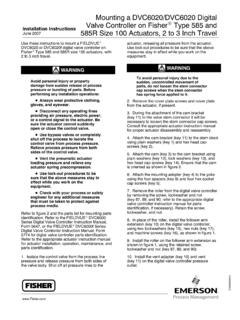
1 Mounting Type DVC5020 or DVC6020 . Installation Instructions Digital Valve Controllers on Fisher November 2004 Type 1051 and 1052. Mounting . ADAPTOR. (KEY 117). CAP SCREW. (KEY 116). MACHINE SCREW. (KEY 95). CAM. (KEY 94). APPLY LUB, SEALANT. 43B8450-B. A7116 / IL. Figure 1. Type DVC5020 or DVC6020 Digital Valve controller Mounted on Type 1052 Size 33 Actuator Use these instructions to mount a FIELDVUEr Type D Use bypass valves or completely DVC5020 or DVC6020 Digital Valve controller on shut off the process to isolate the Fisher Type 1051 and 1052 actuators. Valve from process pressure. Relieve process pressure from both sides of the Valve . Drain the process media WARNING from both sides of the Valve .
2 Avoid personal injury or property D Vent the pneumatic actuator damage from sudden release of loading pressure and relieve any process pressure or bursting of parts. actuator spring precompression. Before performing any maintenance operations: D Use lock-out procedures to be sure that the above measures stay in D Always wear protective clothing effect while you work on the and eyewear. equipment. D Disconnect any operating lines providing air pressure, electric power, D Check with your process or safety or a control signal to the actuator. Be engineer for any additional safety sure the actuator cannot suddenly measures that must be taken to open or close the Valve .
3 Protect against process media. D300924X012 11/2004. Mounting Type DVC5020 or DVC6020 . Digital Valve Controllers on Fisher Installation Instructions Type 1051 and 1052 November 2004. CAP SCREW. (KEY 116). CAM CAP SCREW. (KEY 94) (KEY 59). O-RING. (KEY 60). MACHINE SCREW. (KEY 95). APPLY LUB, SEALANT. 43B8448-B. A7117 / IL. Figure 2. Type DVC5020 or DVC6020 Digital Valve controller with Integrally Mounted Filter Regulator Mounted on Type 1051 Size 40 Actuator Unless otherwise noted, refer to figure 1 or 2 for key Note number locations. For information on the various 1. Isolate the control Valve from the process line actuator Mounting styles and pressure, release pressure from both sides of the positions, see figure 3.
4 Also refer to Valve body, and drain the process media from both the appropriate actuator instruction sides of the Valve . Shut off all pressure lines to the manual. pneumatic actuator, releasing all pressure from the 4. See figure 3. For actuator Mounting styles A and actuator. Use lock-out procedures to be sure that the D, proceed to the note before step 8. For actuator above measures stay in effect while working on the Mounting styles B and C, continue with step 5. equipment. 5. Disconnect the actuator turnbuckle from the lever arm. Note Go to step 12 if the actuator already Note has the cam (key 94) installed. Do not change the position of the rod 2.
5 Mark the positions of the travel indicator and end bearing on the end of the actuator cover. Then, remove the actuator travel turnbuckle. indicator machine screws, travel indicator, and actuator cover cap screws. 6. Loosen the lever clamping bolt in the lever. 3. Remove the cover plate from the actuator 7. Mark the lever/ Valve shaft orientation, and housing. remove the lever. 2. Mounting Type DVC5020 or DVC6020 . Installation Instructions Digital Valve Controllers on Fisher November 2004 Type 1051 and 1052. Valve SERIES OR DESIGN Valve SERIES OR DESIGN. Mounting ACTION(1) BALL/PLUG DISK/BALL 8510B, 8532, CV500. ROTATION TO V250 V150 V200 & V300.
6 V150, ROTATION TO V250 8560. V500. CLOSE CLOSE & 9500. PDTC CCW A A A CW NA B. Right-Hand PDTO CCW B B B CW NA A. PDTC CCW NA D D CW C C. Left-Hand PDTO CCW NA C C CW D D. Left-Hand PDTC CW NA C NA NA NA NA. (Optional) (2) PDTO CW NA D NA NA NA NA. 1. PDTC Push-down-to-close, and PDTO Push-down-to-open. 2. A left hand ball will be required for the 3- through 12-inch Series B and the 14- to 20-inch, with or without attenuator. STYLE A STYLE B. POSITION 1 1 POSITION 1 1. STYLE D. FLOW. STYLE C. 2 4. LEFT-HAND. Mounting 4 2. 3 3. RIGHT HAND Mounting . STYLE D STYLE C. STYLE B. STYLE A POSITION 1 1 POSITION 1 1. FLOW. 2 4. 4 2. 3 3. RIGHT-HAND. 43A6505-A Mounting .
7 A1584-3 LEFT HAND Mounting . NOTES: 1 POSITION 1 IS STANDARD; POSITIONS 2 THROUGH 4. (SHOWN IN DOTTED LINES) ARE ALTERNATIVES. Figure 3. Mounting Styles and Positions for the Type 1051 and 1052 Actuator Note 8. Install the cam (key 94) on the actuator lever with the cam Mounting screws (key 95). 9. For actuator styles A and D, proceed to step 12. The cam has the letter D (direct acting) For actuator styles B and C, continue with step 10. on one side and the letter R (reverse acting) on the other side. Always 10. Slide the lever/cam assembly (cam side first). install the cam with the letter D on the onto the Valve shaft. Orient the lever with the shaft same side as the cam Mounting screw as noted in step 7, and tighten the lever clamping heads (key 95).
8 Bolt. 3. Mounting Type DVC5020 or DVC6020 . Digital Valve Controllers on Fisher Installation Instructions Type 1051 and 1052 November 2004. Note CAUTION. Refer to the appropriate actuator instruction manual to determine the To avoid parts damage, do not distance required between the housing completely stroke the actuator while face and the lever face and to the cover is removed. determine the proper tightening torque for the lever clamping bolt. 11. Connect the turnbuckle and the lever arm. WARNING. 12. For Type 1051 size 33 and 1052 size 20 and 33 actuators, attach an adaptor (key 117) to the To avoid personal injury from moving actuator with four screws (key 116).
9 Then attach the parts, keep fingers and tools clear Digital Valve controller assembly to the adaptor. The while stroking the actuator with the roller on the Digital Valve controller feedback arm will cover removed. contact the actuator cam as it is being attached. Install and tighten four screws (key 116). For additional information concerning Mounting , setup, calibration and maintenance, refer to the For other size 1051 and 1052 actuators, attach the FIELDVUE DVC5000 Series Digital Valve Digital Valve controller assembly to the front access Controllers Instruction Manual - Form 5335 for opening of the actuator. The roller on the Digital DVC5010 Digital controllers, and the FIELDVUE.
10 Valve controller feedback arm will contact the DVC6000 Series Digital Valve Controllers Instruction actuator cam as it is being attached. Install and Manual - Form 5647 for DVC6010 Digital Valve tighten four screws (key 116). controllers. 13. Replace the actuator cover and the travel indicator in the positions that were marked in step 2. Note Note Actuator cover alignment on the Type Emerson Process Management does 1052 actuator can be aided by moving not assume responsibility for the the actuator slightly away from its up selection, use, or maintenance of any travel stop using a regulated air product. Responsibility for the source. If hole alignment cannot be selection, use, or maintenance of any obtained in this manner, temporarily Fisher product remains solely with the loosen the cap screws that secure the purchaser and end-user.