Transcription of Multi Beam Antennas Planning- Limitations & …
1 Application NotesMultibeam Antennas planning Limitations and solutionsDr. Mohamed Nadder Hamdy, PhDJanuary, 20162I. Introduction 3II. After upgrade coverage gaps 3 antenna azimuth plans 4 Coverage holes with twin beam Antennas 4 Coverage holes with tri- beam antenna 4 Coverage holes with a twin beam surrounded by three-sector sites 4 III. PCI planning 5 Background 5 LTE air interface 5 The resource block (RB) 5 Why PCI mod 3? 6 Reference signals-RS vs. users traffic 6 The physical cell identity (PCI) 6 Intra site PCI v-shift planning 7 Problem description 7 Possible six-sector site arrangements 7 Possible nine-sector site arrangements 7 Inter site PCI v-shift planning 8 LTE-FDD case 8 Current networks situations 8 C-RAN case 8 PCI-vshift neighbors plan for tessellation deployments 8IV.
2 Multibeam Antennas and neighbor lists Limitations 9 Background 9 Neighbors Limitations in 3 GPP 9 SIB11 Limitations and 3 GPP releases (Idle mode) 10 SIB11 dimensioning 10 SIB11 calculations 10 SIB11 example 11 3 GPP releases solution 11 Vendors proprietary solutions 11 Multicarrier vs. multibeam expansions 11 Expansion types 11 Neighbor list load calculations 11 Automatic neighbor relations (ANR) 12 Historical 12 LTE case 13V. Conclusion 13VI. References 13 Contents3I. IntroductionAs mobile data traffic continues to rise, there are three main ways to expand networks capacities: densification of sites, adding spectrum, and enhancing through technology upgrades. While the second and third dimensions are costly, operators tend more to densify their networks infrastructures.
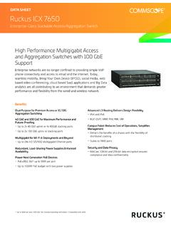
3 In mature networks, densification is achievable through a number of techniques, such as the addition of small cells and macro sectors. While the latter is easier to implement, it faces interference risks as a result of sector overlap. Two single- beam vs. twin beam antenna overlap1 Multibeam Antennas add instantaneous cost-efficient capacity, eliminating the need for new spectrum and sites building, in a minimized overlap pattern design. In this application note, we highlight some of the major challenges and concerns with the deployment of multibeam Antennas deployment together with recommended After upgrade coverage gapsAntenna azimuth plansUpon upgrading from traditional to multibeam Antennas , RF planners might maintain existing panel azimuth with new beam directions (inherited panel azimuth) or preserve their beams, bores plans by changing the panel azimuth (inherited beam azimuth).
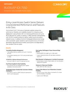
4 This is illustrated in the figure below for a twin beam case. For maintaining beam bores (inherited beam azimuth), a slight change in the new antenna panel bore is made, such that one of its twin beams inherits the former single beam s direction. This deployment might be appealing for adding capacity with minimal disruptions. Two single-beamed (65 )Twin beam (33 )Traditional antennaoriginal azimuthInherited panel azimuthchanged beams azimuthInherited beamazimuth adjusted panel4 Coverage holes with twin beam antennasAs a result of deploying dual- beam Antennas with inherited beam azimuth some coverage gaps might arise. For twin- beam Antennas , rotating ALL sectors by 20 degrees solves this problem, as shown below. Coverage holes with tri- beam antennaFor tri- beam deployments, rotating ALL sectors by 10 degrees eliminates sectors shooting at each other and fills up coverage gaps.
5 This also helps in having a dominant serving cell per area. Coverage holes with a twin beam surrounded by three-sector sitesAgain for the inherited beam azimuth upgrade, as shown in the left figure below, three sectors are found shooting at each other, but no gaps (nulls) are introduced. In the case of inherited panel azimuth antenna upgrade, as in the right-side figure below, no sectors are shooting at each other but three null areas are 20-degree rotation10oProblematicAfter 10 degree rotation5 The first arrangement (inherited beam azimuth) is thus recommended, after necessary tilts adjustments, to overcome the direct shooting bores. III. PCI planningProper physical cell identities (PCI) planning , for LTE networks can result in improved performances. With the introduction of multibeam Antennas , operators have raised some PCI planning concerns that have limited their adoption of such solutions .
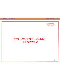
6 In this section, we explore these concerns and propose specific air interface To better understand these PCI planning concerns, let us remind ourselves about the structure of LTE radio LTE frame (10 ms) = 10 sub-frames (1 ms) A sub-frame (1 ms) = 2 time slots (TS) A TS ( ms) = 7 symbols (normal cyclic prefix case) The resource block (RB) A resource block (RB) is two-dimensional: Time (1TS, x-axis) and Frequency (12 subcarriers, y-axis) 100 RB = 20 MHz bandwidth (maximum LTE bandwidth before carrier aggregation).Now the system needs to insert cell reference signals (RS) into fixed predetermined Time (symbol) and Frequency (subcarrier) locations. These are marked in red in the following diagram, depicting a system with one antenna port. Notice that Time locations are at symbols 0 and 4.
7 Frequency locations depend on v and v-shift. Inherited beam azimuth swapInherited panel azimuth swap6V-shift is used to shift the RS frequency allocations between neighboring sectors, reducing interference. The v-shift = PCI mod 6 for systems with one antenna port (v+0 to v+5) = PCI mod 3 for systems with two or four antenna ports (v+0 to v+2) Why PCI mod 3? Here we consider a system with two antenna ports (2x2 MIMO). The RS allocations of the first and second antenna ports are shown in red and blue, respectively. However, each port blocks its transmission in the other ports RS time/freq allocations (shown shaded). This gives room for only two possible v-shift signals-RS vs. users trafficWithout applying v-shifts, neighboring sectors RSes might interfere each other. With v-shift applied, neighboring sectors RSes won t collide any more.
8 However, at high loads, users traffic can still impact the RSes, diminishing the benefits of v-shifts. The physical cell identity (PCI) The PCI is analogous to the UMTS PSC. The total of 504 PCI s are grouped as follows ID = 0 to 2, group = 0 to 167 PCI = ID + 3*group PCIs are, thus, divided into 168 groups with three IDs in each shows 168 groups (sites) with three sectors per site (group), such that each sector has a unique PCI mod 3. For example, the highlighted group 1 has sectors PCI = 3, 4 and arrangements are further proposed for better PCI spreading, preserving mod 3 uniqueness between sectorsThe PCI ID (0 to 2) is used to derive the primary sync sequence and the PCI group is used to derive the secondary sync sequence (0 to 167).Intra site PCI v-shift planning Problem descriptionSince normal LTE deployments use 2x2 MIMO (with two antenna ports), v-shift will always be limited by PCI mod 3, from 0 to 2 only.
9 This has raised concerns about complicated PCI planning threatening the deployment of multibeam six-sector site arrangements As a workaround, for dual-band Antennas in six-sector arrangements, the best that can be done is to use two PCI groups per site to avoid having the same PCI mod 3 (v-shift) values between direct adjacent sectors. The figure below shows the possible arrangements of assigning two PCI groups to each site. The sector color indicates the same PCI group and the numbers reflect PCI mod 3 v-shift values. Possible nine-sector site arrangements Similarly, the case with tri- beam Antennas /nine-sector sites can be treated by assigning three PCI groups per site. A number of arrangements are possible, as displayed below. Problematic!!Arrangement 1 Arrangement 2 Arrangement 3 Arrangement 4 Arrangement 58 Intersite PCI v-shift planningSome concerns were raised also about potential conflicts between neighboring sites as well especially in the case of nine-sector caseThe LTE-FDD neighboring sites are not phase synchronized.
10 Consequently, the OFDM symbols 0 and 4 carrying the reference signal (RS) won t be in sync and have much less of a chance to collide in the neighbor site s v-shift conflicts the example shown above, site 1 sector A and site 2 sector C have the same PCI v-shift values and are direct neighbors. Since they are not phase synchronized, symbol 0 of site1A lands on symbol 5 of site 2C. In this case, the chances of landing on the same OFDM symbol are much less. As a result, PCI v-shift planning will be more useful for the same site s sectors, which are in exact phase networks situationsMoreover, the majority of operators won t face neighbors, PCI v-shift conflict issue, with multibeam Antennas , for two reasons:1. Their deployments are not following the uniform tessellation Modern SON should be able to configure eNode B s PCI values caseWith the C-RAN concept, baseband units (BBU) are centralized as a shared pool resource for their connected remote radio units (RRU).