Transcription of Navigation Remote Controller (Wired Remote Controller) …
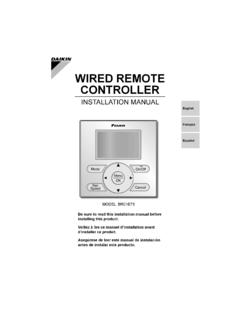
1 EDUS721438 Navigation Remote Controller (Wired Remote Controller )BRC1E73 EDUS721438 Contents1 Contents1. Specifications .. 22. Dimensions .. 33. Restrictions .. 44. Operation Safety Considerations .. Button Locations and Names and Functions .. Basic Quick Menu Options .. Maintenance .. Reference 545. Installation Manual .. Safety Considerations .. Accessories .. Remote Controller Installation Procedure .. Functions and Menu Items of Remote Controller Power-on .. Field Test Procedure for Checking Error History .. Adding Maintenance Contact Information .. Confirming Registered Clock & Calendar .. Language .. 76 SpecificationsEDUS7214382 BRC1E731. SpecificationsNew Remote Controller BRC1E73 Dimension (H W D) 3/4 4 3/4 3/4 LCDD isplay size (H W) 25/32 2 13/16 Display methodFull dot method (dot 160 255)BacklightYes (Background color: white)ColorFresh whiteEDUS721438 DimensionsBRC1E7332.
2 DimensionsC: 3D091305 AUnit: inRestrictionsEDUS7214384 BRC1E733. Restrictions1. In the case of 2 Remote control : Connectable : Not connectable Due to the limited power supply capacity, there are some restrictions when controlling 2 Remote controllers.<Common restriction for SkyAir and VRV >When controlling one indoor unit with 2 Remote controllers, the Remote Controller operated first turns the backlight on.<Restriction for VRV only>Adaptor for wiring (KRP1C*) or power supply adaptor for indoor unit PCB (X18A or X35A) cannot be used for 2 Remote Controller system. When controlling 2 Remote controllers, the following functions cannot be set with the sub Remote Schedule- Auto Changeover- Setback- Dual Setpoint(For the details, refer to )2. In the case of Centralised Remote Controller connection. When connecting centralised control equipment, the following functions can be re-enabled with a field Schedule- Auto Changeover- SetbackMainBRC1E73 BRC1E72 WirelessBRC4**BRC7**SubBRC1E739 BRC1E72 9 WirelessBRC4**BRC7** EDUS721438 Operation ManualBRC1E7354.
3 Operation Manual3P243520-7 NEnglish 1 NoticesSafety Considerations Items to be Strictly Observed .. 2 Button Locations and Descriptions .. 4 Basic OperationCool/Heat/Auto/Fan Operation .. 10 Dry Mode .. 13 Setback .. 14 Ventilation Mode .. 15 Setting the Cool / Heat Changeover Master .. 16 Key Lock .. 19 Quick ReferenceMain Menu Items .. 20 Menu OptionsNavigating the Main Menu Screen .. 22 Airfl ow Direction .. 23 Individual Airfl ow Direction .. 25 Ventilation .. 28 Schedule .. 30 Off Timer .. 35 Maintenance Information .. 37 Confi guration .. 38 Current Settings .. 42 Clock & Calendar .. 42 Daylight Saving Time .. 45 Language .. 48 MaintenanceReset Filter Indicator .. 48 Maintaining the Unit and LCD Display .. 49 Reference InformationError Code Display .. 50 After-sale Service .. 51 111/27/2014 10:34:34 AMOperation Considerations3P243520-7N2 EnglishSafety ConsiderationsThe original instructions are written in English.
4 All other languages are translation of the original these SAFETY CONSIDERATIONS carefully before operating the Remote the customer to operate and maintain the Remote customers that they should store this Operations Manual with the Installation Manual for future of WARNING and CAUTION Symbols:WARNINGI ndicates a potentially hazardous situation which, if not avoided, could result in death or serious a potentially hazardous situation which, if not avoided, may result in minor or moderate may also be used to alert against unsafe situations that may result in equipment or property-damage accidents following pictograms are used in this manual. Never follow the instructions water and moisture wet hands not modify or repair the Remote Controller . Consult your Daikin dealer for any modifi cation or for not relocate or reinstall the Remote Controller by yourself. Improper installation may result in electric shocks or fi re.
5 Consult your Daikin dealer to relocate or for any not use fl ammable materials ( , hairspray or insecticide) near the Remote not clean the product with organic solvents such as paint use of organic solvents may cause cracking, damaging the product, causing electric shocks, or fi the dealer if the Remote Controller was submerged under water due to a natural disaster, such as a fl ood or not operate the Remote Controller at this time or a malfunction, electric shock, or fi re can 211/27/2014 10:34:34 AMEDUS721438 Operation ManualBRC1E7373P243520-7 NEnglish 3 Items to be Strictly Observed CAUTIONDo not allow children to play with the Remote Controller to avoid causing damage to the product. Never disassemble the Remote Controller . Touching the interior parts may result in electric shocks or fi your Daikin dealer for internal inspections and not touch the Remote Controller buttons with wet fi ngers.
6 Touching the buttons with wet fi ngers can cause an electric not wash the Remote Controller . Doing so may cause electric leakage and result in electric shocks or fi let the Remote Controller to get wet. Water can cause damage to the Remote Controller , and may cause an electric shock or fi press the button of the Remote Controller with a hard and pointed Remote Controller may be pull or twist the electric wire of the Remote Controller . It may cause the unit to not wipe the Remote Controller with benzine, thinner, chemical dustcloth, Remote Controller may get discolored or the coating peeled off. If it is heavily dirty, soak a cloth in water-diluted neutral detergent, squeeze it well and wipe the Remote Controller clean. And wipe it with another dry 311/27/2014 10:34:34 AMOperation Locations and Descriptions3P243520-7N4 EnglishOn/OffModeFanSpeedCancelButton Locations and DescriptionsFunctions other than basic operation items ( , On/Off, Operation Mode, Fan Speed, and Setpoint) are set from the menu screen.
7 NOTE Do not install the Remote Controller in places exposed to direct sunlight, the LCD will be not pull or twist the Remote Controller cord, the Remote Controller may be not use objects with sharp ends to press the buttons on the Remote Controller , damage may result. 2. Fan speed control button 3. Menu/OK button 8. On/Off button10. Cancel button 9. Operation lamp11. LCD (with backlight) 4. Up button 5. Down button 6. Right button 7. Left button 1. Operation mode selector 411/27/2014 10:34:35 AMEDUS721438 Operation ManualBRC1E7393P243520-7 NEnglish 5 Operation mode selector button1. Press this button to select the operation mode of your preference. (See page 10.)Available modes vary with the indoor unit * speed control button2. Press this button to select the fan speed of your preference. (See page 11.)Available fan speeds vary with the indoor * unit button3.
8 Used to enter the main menu. (See page 20 for the menu items.)Used to enter the selected item. Up button 4. Used to raise the setpoint. The item above the current selection will be highlighted.(The highlighted items will be scrolled continuously when the button is continuously pressed.)Used to change the selected item. Down button 5. Used to lower the setpoint. The item below the current selection will be highlighted.(The highlighted items will be scrolled continuously when the button is continuously pressed.)Used to change the selected item. Right button 6. Used to highlight the next items on the right-hand screen is scrolled in the right-hand button 7. Used to highlight the next items on the left-hand screen is scrolled in the left-hand button8. Press this button and system will start. Press this button again to stop the system. Operation lamp9. This lamp illuminates solid green during normal lamp fl ashes if an error occurs.
9 Cancel button10. Used to return to the previous screen. LCD (with backlight)11. The backlight will be illuminated for approximately 30 seconds by pressing any button. If two Remote controllers are used to control a single indoor unit, only the Controller accessed fi rst will have backlight 511/27/2014 10:34:35 AMOperation and Functions3P243520-7N6 EnglishLiquid Crystal DisplayThree types of display mode (Standard, Detailed and Simple) are available. Standard display is set by default. Detailed and Simple displays can be selected in the main menu. (See page 40.) Standard display Set toCoolHeat74F70 FAutoCoolThis function is not available<Standard display example>6. Ventilation2. Fan Speed1. Operation ( ) Key Lock3. Setpoint4. Stand by for Defrost/ Hot start5. Message10. Changeover controlled by the master indoor centralized control8. ( ) ScheduledAUTOERVAIRPURIFYCENTRALCONTROLM ASTERCONTROLLEDSETBACKSTANDBY Detailed display The airfl ow direction, clock, and selectable item appear on Detailed display screen in addition to the items appearing on Standard :03 ASet to74 FReturnSettingAutoCool14.
10 Selectable Display Item12. Airflow Direction (Displayed only when the indoor unit is turned on.)13. Current Day/Time (12/24 hour time display)<Detailed display example 1>AUTOERVAIRPURIFYCENTRALCONTROLMASTERCONT ROLLEDSETBACKSTANDBYR eturnSettingAutoCool<Detailed display example 2>No Airflow Direction display (with no airflow direction settings) No Fan speed display (with no fan speed control function)No Selectable Display Item(with no selectable display item selected)No Clock display (when the clock has not been set yet)15. ( ) Unable to schedule--:--CENTRALCONTROLMASTERCONTROL LEDSETBACKAUTOERVAIRPURIFYSTANDBYN ames and 611/27/2014 10:34:35 AMEDUS721438 Operation ManualBRC1E73113P243520-7 NEnglish 7 Simple display 70F74F74 FAutoCoolRoomSTANDBYSet toHeat CoolSETBACK<Simple display example>2. Fan speed3. Setpoint1. Operation Display Stand by for Defrost/ Hot start Note for all display modes Depending on the fi eld settings, while the indoor unit is stopped, OFF may be displayed instead of the operation mode and/or the setpoint may not be 711/27/2014 10:34:35 AMOperation ManualEDUS72143812 BRC1E733P243520-7N8 EnglishNames and FunctionsOperation mode1.