Transcription of NI 9205 Datasheet - National Instruments
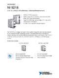
1 DATASHEETNI 920516 AI Differential/32 AI Single-Ended, 200 mV to 10 V, 16 Bit,250 kS/s Aggregate DSUB or push-in spring terminal connectivity 250 V RMS, CAT II, channel-to-earth isolation(spring terminal); 60 V DC, CAT I, channel-to-earth isolation (DSUB)The NI 9205 is a C Series module for use with any CompactDAQ or CompactRIO channel has programmable input ranges of 200 mV, 1 V, 5 V, and 10 V. To protectagainst signal transients, the NI 9205 includes 30 V of overvoltage protection between inputchannels and common (COM). In addition, the NI 9205 also includes a channel-to-earth-ground isolation barrier for safety, noise immunity, and high common-mode voltage range. NI 9205 NI 9205 Getting Started Guide Spring-Terminal NI 9940 Backshell Kit (785080-01) Cable DSUB Cable, 1 m (778621-01)Kit ContentsAccessoriesDSUBF ront-Mount NI 9923 Screw-Terminal Block (781503-01) 37-Pin DSUB to Screw-Terminal Block with Horizontal DIN-Rail Mount (778673-01) NI C Series OverviewNI provides more than 100 C Series modules for measurement , control, and communicationapplications.
2 C Series modules can connect to any sensor or bus and allow for high-accuracymeasurements that meet the demands of advanced data acquisition and control applications. measurement -specific signal conditioning that connects to an array of sensors and signals Isolation options such as bank-to-bank, channel-to-channel, and channel-to-earth ground -40 C to 70 C temperature range to meet a variety of application and environmentalneeds Hot-swappableThe majority of C Series modules are supported in both CompactRIO and CompactDAQplatforms and you can move modules from one platform to the other with no combines an open-embedded architecturewith small size, extreme ruggedness, and C Seriesmodules in a platform powered by the NI LabVIEW reconfigurable I/O (RIO) architecture. Each systemcontains an FPGA for custom timing, triggering, andprocessing with a wide array of available modular I/O tomeet any embedded application is a portable, rugged data acquisition platformthat integrates connectivity, data acquisition, and signalconditioning into modular I/O for directly interfacing to anysensor or signal.
3 Using CompactDAQ with LabVIEW, youcan easily customize how you acquire, analyze, visualize, andmanage your measurement | | NI 9205 DatasheetSoftwareLabVIEW Professional Development System for Windows Use advanced software tools for large project development Generate code automatically using DAQ Assistant and InstrumentI/O Assistant Use advanced measurement analysis and digital signal processing Take advantage of open connectivity with DLLs, ActiveX, and .NETobjects Build DLLs, executables, and MSI installersNI LabVIEW FPGA Module Design FPGA applications for NI RIO hardware Program with the same graphical environment used for desktop andreal-time applications Execute control algorithms with loop rates up to 300 MHz Implement custom timing and triggering logic, digital protocols, andDSP algorithms Incorporate existing HDL code and third-party IP including Xilinx IPgenerator functions Purchase as part of the LabVIEW Embedded Control and MonitoringSuiteNI LabVIEW Real-Time Module Design deterministic real-time applications with LabVIEW graphical programming Download to dedicated NI or third-party hardware for reliableexecution and a wide selection of I/O Take advantage of built-in PID control, signal processing.
4 Andanalysis functions Automatically take advantage of multicore CPUs or setprocessor affinity manually Take advantage of real-time OS, development and debuggingsupport, and board support Purchase individually or as part of a LabVIEW suiteInput CircuitryThe NI 9205 channels share a common ground (COM) that is isolated from other modules inthe system. All channels share a programmable gain instrumentation amplifier and aremultiplexed to an ADC. Each channel also has 30 V overvoltage 9205 Datasheet | National Instruments | 3 Figure 1. Input Circuitry for One Analog Input Channel on the NI 9205AI+AI COMAISENSENI 9205 TriggerTrigFiltered Differential Amplifier16-bit Isolated ADC ADCMUXPGIANI 9205 SpecificationsThe following specifications are typical for the range -40 C to 70 C unless otherwise voltages are relative to COM unless otherwise Do not operate the NI 9205 in a manner not specified in this misuse can result in a hazard.
5 You can compromise the safety protectionbuilt into the product if the product is damaged in any way. If the product isdamaged, return it to NI for ,832 hours at 25 C; Bellcore Issue 6,Method 1, Case 3, Limited Part Stress MethodAnalog Input CharacteristicsNumber of channels16 differential/32 single-ended channelsADC resolution16 bitsDNLNo missing codes guaranteedConversion time (maximum sampling rate)CompactRIO & s (250 kS/s)R Series Expansion s (222 kS/s)Input couplingDCNominal input ranges 10 V, 5 V, 1 V, VMinimum overrange, 10 V range4%Maximum working voltage for analoginputs (signal + common mode)Each channel must remain within V ofCOMI nput impedance (AI-to-COM)Powered on>10 G in parallel with 100 pFPowered k minimumInput bias current 100 pA4 | | NI 9205 DatasheetCrosstalk, at 100 kHzAdjacent channels-65 dBNon-adjacent channels-70 dBAnalog bandwidth370 kHzOvervoltage protectionAI channel, 0 to 31 30 V, one channel onlyAISENSE 30 VSettling time for multichannel measurements, accuracy, all ranges 120 ppm of full-scale step, 8 LSB4 s convert interval 30 ppm of full-scale step, 2 LSB8 s convert intervalAnalog triggersNumber of triggers1 Resolution10 bits, 1 in 1,024 Bandwidth, -3 dB370 kHzAccuracy 1% of full scaleScaling coefficients 10 V range328 V/LSB 5 V V/LSB 1 V V/LSB V V/LSBCMRR, DC to 60 Hz100 dBFigure 2.
6 CMRR, AI+ to AI-AI < > CMRR406080100120601001 k10 k100 kFrequency (Hz)CMRR (dB)140NI 9205 Datasheet | National Instruments | 5 Analog Input Absolute AccuracyThe following values are based on calibrated scaling coefficients, which are stored in theonboard 1. Absolute accuracyRangeAccuracy at Full Scale1 Random Noise2, Sensitivity3 10 V6,230 V237 V V 5 V3,230 V121 V V 1 V692 V29 V V V175 V15 V VResidual gain error 10 V range115 ppm of reading 5 V range135 ppm of reading 1 V range155 ppm of reading V range215 ppm of readingGain tempco11 ppm/ CReference tempco5 Residual offset error 10 V range20 ppm of range 5 V range20 ppm of range 1 V range25 ppm of range V range40 ppm of rangeOffset tempco 10 V range44 ppm of range/ C 5 V range47 ppm of range/ C 1 V range66 ppm of range/ C V range162 ppm of range/ CINL error76 ppm of range1 Absolute accuracy values at full scale on the analog input channels assume the device is operatingwithin 70 C of the last external calibration and are valid for averaging 100 samples immediatelyfollowing mode3 Sensitivity is a function of noise and indicates the smallest voltage change that can be | | NI 9205 DatasheetAnalog Input Accuracy FormulasAbsolute Accuracy
7 = Reading * Gain Error + Range * Offset Error + Noise UncertaintywhereGain Error = Residual Gain Error + Gain Tempco * Temp Change from Last Internal Cal+ Reference Tempco * Temp Change from Last External CalOffset Error = Residual Offset Error + Offset Tempco * Temp Change from Last InternalCal + INL ErrorNoise Uncertainty = (Random Noise * 3) / 100 for a coverage factor of 3 andaveraging 100 pointsAbsolute accuracy at full scale on the analog input channels is determined using the followingassumptions:Temp Change from Last External Cal = 70 CTemp Change from Last Internal Cal = 1 CNumber of Readings = 100 Coverage Factor = 3 For example, on the 10 V range, the absolute accuracy at full scale is as follows:Gain Error = 115 ppm + 11 ppm * 1 + 5 ppm * 70 Gain Error = 476 ppmOffset Error = 20 ppm + 44 ppm * 1 + 76 ppmOffset Error = 140 ppmNoise Uncertainty = (237 V * 3) / 100 Noise Uncertainty = 72 VAbsolute Accuracy = 10 V * 476 ppm + 10 V * 140 ppm + 72 VAbsolute Accuracy = 6,231 V, rounds to 6,230 VDigital CharacteristicsNumber of channels1 digital input channel, 1 digital output channelOvervoltage protection 30 VDigital logic levelsInput high, V4 The digital input and digital output channel are supported only in FPGA Interface mode 9205 Datasheet | National Instruments | 7 Input low, VILM inimum0 VOutput high, VOH, sourcing 75 VOutput low, VOH, sinking 250 AMinimum0 VExternal digital triggersSourcePFI0 Delay100 ns maximumPower RequirementsPower consumption from chassisActive mode625 mW maximumSleep mode15 mWThermal dissipation (at 70 C)
8 Active mode625 mW maximumSleep mode15 mWPhysical CharacteristicsIf you need to clean the module, wipe it with a dry For two-dimensional drawings and three-dimensional models of the C Seriesmodule and connectors, visit and search by module terminal mm2 to mm2 (26 AWG to 16 AWG)copper conductor wireWire strip length10 mm ( in.) of insulation stripped fromthe endTemperature rating90 C, minimumWires per spring terminalOne wire per spring terminal; two wires perspring terminal using a 2-wire mm2 to mm28 | | NI 9205 DatasheetConnector securementSecurement typeScrew flanges providedTorque for screw N m ( lb in.)WeightNI 9205 with spring terminal163 g ( oz)NI 9205 with DSUB148 g ( oz)Safety VoltagesConnect only voltages that are within the following limits:Maximum voltage5 Channel-to-COM 30 V DCNI 9205 with Spring Terminal Isolation VoltagesChannel-to-channelNoneChannel-to -earth groundContinuous250 V RMS, measurement Category IIWithstand up to 5,000 m3,000 V RMS, verified by a 5 sdielectric withstand testMeasurement Category II is for measurements performed on circuits directly connected to theelectrical distribution system.
9 This category refers to local-level electrical distribution, such asthat provided by a standard wall outlet, for example, 115 V for or 230 V for Do not connect the NI 9205 with spring terminal to signals or use formeasurements within measurement Categories III or 9205 with DSUB Isolation VoltagesChannel-to-channelNoneChannel-to -earth groundContinuous60 V DC, measurement Category IWithstandup to 2,000 m1,000 V RMS, verified by a 5 s dielectricwithstand testup to 5,000 m500 V RMS5 The maximum voltage that can be applied or output between AI and COM without creating a 9205 Datasheet | National Instruments | 9 measurement Category I is for measurements performed on circuits not directly connected tothe electrical distribution system referred to as MAINS voltage. MAINS is a hazardous liveelectrical supply system that powers equipment. This category is for measurements of voltagesfrom specially protected secondary circuits.
10 Such voltage measurements include signal levels,special equipment, limited-energy parts of equipment, circuits powered by regulated low-voltage sources, and Do not connect the NI 9205 with DSUB to signals or use formeasurements within measurement Categories II, III, or measurement Categories CAT I and CAT O are equivalent. These test andmeasurement circuits are for other circuits not intended for direct connection to theMAINS building installations of measurement Categories CAT II, CAT III, orCAT (UL)Class I, Division 2, Groups A, B, C, D, T4;Class I, Zone 2, AEx nA IIC T4 GcCanada (C-UL)Class I, Division 2, Groups A, B, C, D, T4; ExnA IIC T4 GcEurope (ATEX) and International (IECEx)Ex nA IIC T4 GcSafety and Hazardous Locations StandardsThis product is designed to meet the requirements of the following electrical equipment safetystandards for measurement , control, and laboratory use: IEC 61010-1, EN 61010-1 UL 61010-1, CSA No.